LS656 데이터 시트보기 (PDF) - STMicroelectronics
부품명
상세내역
제조사
LS656 Datasheet PDF : 15 Pages
| |||
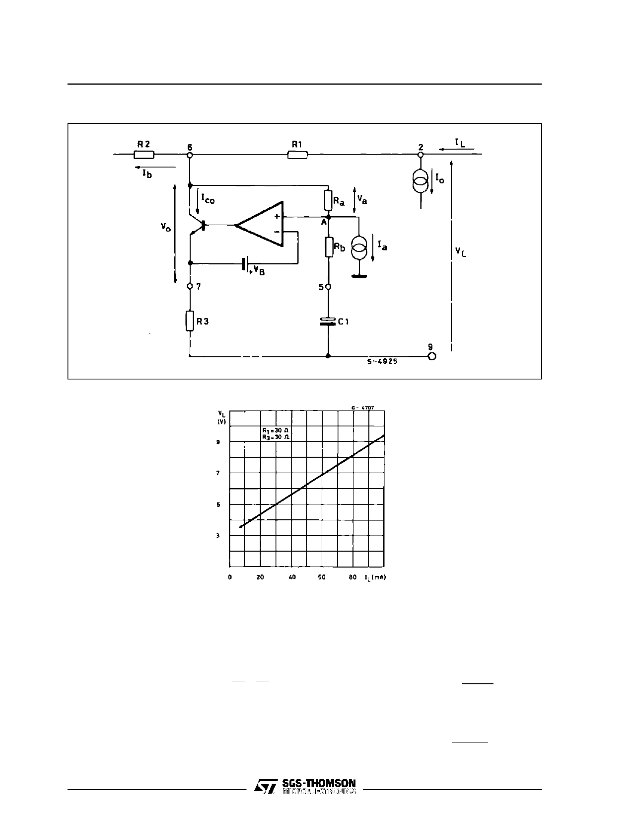
LS656
Figure 6 : Circuit Configuration of the Shunt Regulator.
Figure 7 : DC Characteristic.
2. Two to Four Wires Conversion
TheLS656 performsthe two wires (line) to four wires
(microphone, earphone) conversion by means of a
Wheatstone bridge configuration so obtaining the
proper decoupling between sending and receiving
signals (see fig. 8).
For
a
perfect balancing of
the
bridge
ZL
ZB
=
R1
R2
The AC signal from the microphone is sent to one
diagonalof the bridge (pin 6 and 9). A small percent-
age of the signal power is lost on ZB (being ZB
>> ZL) ; the main part is sent to the line via R1. In re-
ceiving mode, the AC signal coming from the line is
6/15
sensed across the second diagonal of the bridge
(pin 11 and 10). After amplification it is appliedto the
receiving capsule.
The impedance ZM is simulated by the shunt regu-
lator that is also intended to work as a transconduc-
tance amplifier for the transmission signal.
The
impedance
ZM
is
defined
as
∆V6 − 9
∆I6 − 9
From fig. 6 considering C1 as a short circuit for AC
signal, any variation ∆V6 generates a variation :
∆V7
=
∆VA
=
∆V6
⋅
Rb
Ra + Rb
Share Link: 