MAX1760(2001) 데이터 시트보기 (PDF) - Maxim Integrated
부품명
상세내역
제조사
MAX1760 Datasheet PDF : 12 Pages
| |||
0.8A, Low-Noise, 1MHz,
Step-Up DC-DC Converter
OUT
IC POWER
2.15V
ON
UNDERVOLTAGE LOCKOUT
REF
GND
CLK/SEL
FB
ISET
ON
RDY
REFERENCE
1.25V
REF GND
MAX1760
STARTUP
EN OSCILLATOR Q
CONTROLLER
D
EN
OSC
OSCILLATOR
1MHz
CLK/SEL
MODE
EN
OSC
MODE
FB
ISET
POUT
PCH
LX
NCH
PGND
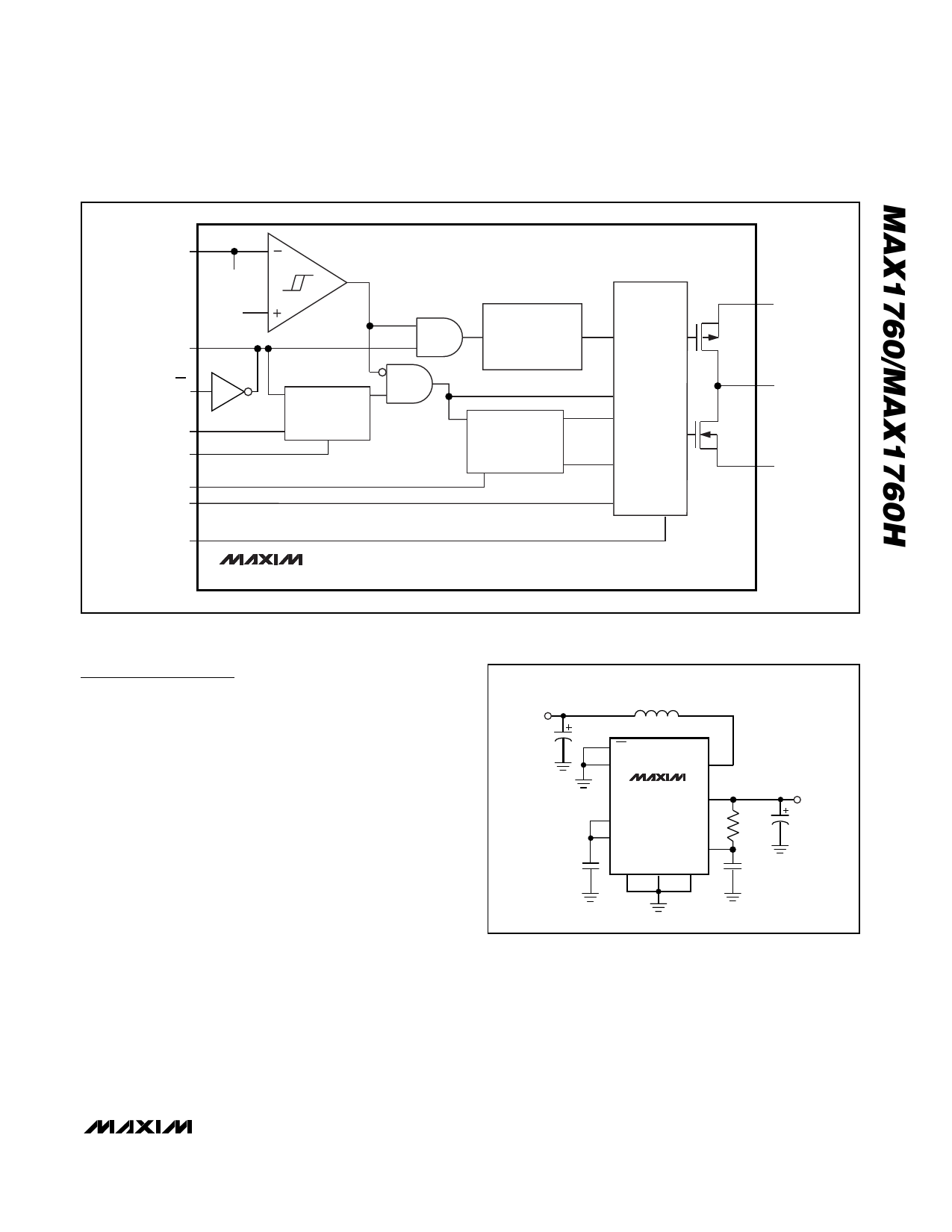
Figure 1. Functional Diagram
Detailed Description
The MAX1760 is a highly efficient, low-noise power sup-
ply for portable RF and hand-held instruments. It com-
bines a boost switching regulator, N-channel power
MOSFET, P-channel synchronous rectifier, precision
reference, and shutdown control (Figure 1).
The DC-DC converter boosts a 1-cell to 3-cell battery
voltage input to a fixed 3.3V or adjustable voltage
between 2.5V and 5.5V. An external Schottky diode is
required for output voltages greater than 4V. The
MAX1760 guarantees startup with an input voltage as
low as 1.1V and remains operational down to an input
of just 0.7V. It is optimized for use in cellular phones
and other applications requiring low noise and low qui-
escent current for maximum battery life. It features
fixed-frequency operation at medium and heavy loads,
but at light loads, switches only as needed for optimum
efficiency. This device is also capable of constant-fre-
quency (1MHz), low-noise PWM operation at all load
currents, or frequency-synchronized PWM operation
when connected to an external clock. Table 1 lists
some typical outputs. Shutdown reduces quiescent cur-
rent to just 1µA. Figure 2 shows the standard applica-
tion circuit for the MAX1760.
VIN = 2.4V
3.3µH
33µF
ON
CLK/SEL
LX
MAX1760
POUT
0.22µF
ISET
REF
OUT
FB GND PGND
VOUT = 3.3V,
800mA
4.7Ω
100µF
0.68µF
Figure 2. Standard Application Circuit
Step-Up Converter
During DC-DC converter operation, the internal N-chan-
nel MOSFET switch turns on for the first part of each
cycle, allowing current to ramp up in the inductor and
store energy in a magnetic field. During the second
part of each cycle, the MOSFET turns off and inductor
current flows through the synchronous rectifier to the
_______________________________________________________________________________________ 7
Share Link: 