MAX1832(2003) 데이터 시트보기 (PDF) - Maxim Integrated
부품명
상세내역
제조사
MAX1832
(Rev.:2003)
(Rev.:2003)
Maxim Integrated

MAX1832 Datasheet PDF : 12 Pages
| |||
High-Efficiency Step-Up Converters with
Reverse Battery Protection
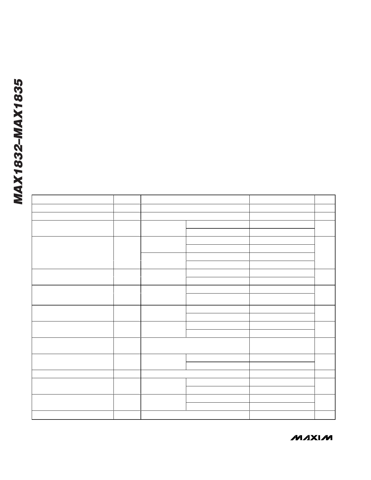
ABSOLUTE MAXIMUM RATINGS
BATT, LX to GND.........................................................-6V to +6V
LX to OUT ....................................................................-6V to +1V
SHDN to GND..............................................-6V to (VOUT + 0.3V)
OUT, FB, RST TO GND ............................................-0.3V to +6V
LX Current ................................................................................1A
Continuous Power Dissipation (TA = +70°C)
6-Pin SOT23 (derate 9.1mW/°C above +70°C) ...........727mW
6-Pin 3mm ✕ 3mm TDFN (derate 24.4mW/°C
above +70°C) ............................................................1951mW
Operating Temperature Range ...........................-40°C to +85°C
Junction Temperature ......................................................+150°C
Storage Temperature Range .............................-65°C to +150°C
Lead Temperature (soldering, 10s) ................................+300°C
Stresses beyond those listed under “Absolute Maximum Ratings” may cause permanent damage to the device. These are stress ratings only, and functional
operation of the device at these or any other conditions beyond those indicated in the operational sections of the specifications is not implied. Exposure to
absolute maximum rating conditions for extended periods may affect device reliability.
ELECTRICAL CHARACTERISTICS
(V SHDN = +1.5V, VOUT = +3.3V, VBATT = +2V, GND = 0, TA = -40°C to +85°C. Typical values are at TA = +25°C, unless otherwise
noted.) (Note 1)
PARAMETER
Output Range
Battery Input Range
Startup Battery Input Voltage
Output Voltage
FB Trip Voltage
FB Input Bias Current
N-Channel On-Resistance
P-Channel On-Resistance
P-Channel Catch-Diode Voltage
N-Channel Switch Current Limit
Switch Maximum On-Time
Synchronous Rectifier Zero-
Crossing Current
Quiescent Current into OUT
(Note 2)
Shutdown Current into OUT
SYMBOL
VOUT
VBATT
VSU
VOUT
VFB
IFB
RNCH
RPCH
IMAX
tON
CONDITIONS
MAX1832/MAX1834
RLOAD = 2.6kΩ
MAX1833EUT/
MAX1835EUT
TA = +25°C
TA = -40°C to +85°C
TA = +25°C
TA = -40°C to +85°C
MAX1833ETT30
TA = +25°C
TA = -40°C to +85°C
MAX1832/
MAX1834
MAX1832/
MAX1834,
VFB = +1.3V
VOUT = +3.3V
ILX = 100mA
TA = +25°C
TA = -40°C to +85°C
TA = +25°C
TA = -40°C to +85°C
TA = +25°C
TA = -40°C to +85°C
VOUT = +3.3V
ILX = 100mA
TA = +25°C
TA = -40°C to +85°C
ILX = 100mA, PCH off, VOUT = +3.5V,
VFB = +1.3V
VOUT = +3.3V
TA = +25°C
TA = -40°C to +85°C
VOUT = +3.3V
TA = +25°C
TA = -40°C to +85°C
VOUT = +3.5V,
VFB = +1.3V
TA = +25°C
TA = -40°C to +85°C
VOUT = +3.5V, VSHDN = VFB = 0V
MIN
2.0
1.5
3.225
3.208
2.94
2.925
1.208
1.204
TYP
1.22
1.24
3.290
3.0
1.228
3.5
4.0
0.4
0.5
MAX
5.5
5.5
1.5
3.355
3.372
3.06
3.075
1.248
1.252
20
1.2
1.5
1.3
1.6
UNITS
V
V
V
V
V
nA
Ω
Ω
0.73
V
435
525
615
mA
400
650
3.5
5
6.5
µs
2
17
34
mA
0
39
2.5
7.0
µA
8.0
0.05
1
µA
2 _______________________________________________________________________________________
Share Link: