MAX1837 데이터 시트보기 (PDF) - Maxim Integrated
부품명
상세내역
제조사
MAX1837 Datasheet PDF : 15 Pages
| |||
MAX1836/MAX1837
24V Internal Switch, 100% Duty Cycle,
Step-Down Converters
INPUT
4.5V OR 24V
CIN
IN
SHDN
VSENSE
RQ
S
MAXIMUM
OFF-TIME
DELAY
Q
TRIG
MAX1836
MAX1837
Q
TRIG
MAXIMUM
ON-TIME
DELAY
OUTPUT
LX
L1
3.3V OR 5V
D1
COUT
OUT
FB
100mV
VSET
1.25V
GND
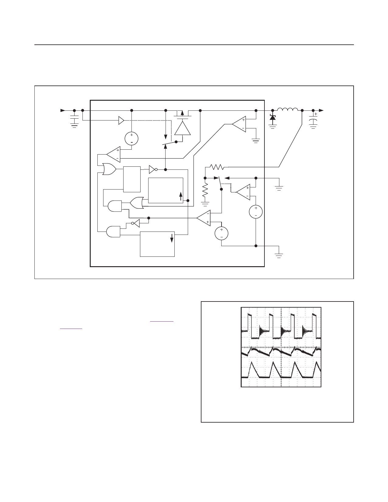
Figure 3. Functional Diagram
When the output voltage is too low, an error compara-
tor sets a flip-flop, which turns on the internal p-channel
MOSFET and begins a switching cycle (Figure 3). As
shown in Figure 4, the inductor current ramps up linearly,
charging the output capacitor and servicing the load. The
MOSFET turns off when the current limit is reached, or
when the maximum on-time is exceeded while the output
voltage is in regulation. Otherwise, the MOSFET remains
on, allowing a duty cycle up to 100% to ensure the lowest
possible dropout voltage. Once the MOSFET turns off, the
flip-flop resets, diode D1 turns on, and the current through
the inductor ramps back down, transferring the stored
energy to the output capacitor and load. The MOSFET
remains off until the 0.5μs minimum off-time expires and
the inductor current ramps down to zero, and the output
voltage drops back below the set point.
10V
A
0
3.3V
B
500mA
0
C
4µs/div
CIRCUIT OF FIGURE 2, VIN = 12V
A. VLX, 5V/div
B. VOUT = 3.3V, 20mV/div, 200mA LOAD
C. INDUCTOR CURRENT, 500mA/div
Figure 4. Discontinuous-Conduction Operation
www.maximintegrated.com
Maxim Integrated │ 8
Share Link: 