MAX212 데이터 시트보기 (PDF) - Maxim Integrated
부품명
상세내역
제조사
MAX212 Datasheet PDF : 8 Pages
| |||
+3V-Powered, Low-Power,
True RS-232 Transceiver
ABSOLUTE MAXIMUM RATINGS
Supply Voltages
VCC .....................................................................-0.3V to +4.6V
V+ ............................................................(VCC - 0.3V) to +7.4V
V- ........................................................................-7.4V to +2.0V
LN ..............................................................-0.3V to (V+ + 1.0V)
LP.......................................................(V- - 1.0V) to (V+ + 0.3V)
InTp_uItNV, oS–—lDta,gEeNs ..............................................-0.3V to (V+ + 0.3V)
R_IN...................................................................................±25V
Output Voltages
T_OUT ................................................................................±15V
R_OUT ........................................................-0.3V to (V+ + 0.3V)
Short-Circuit Duration, T_OUT.....................................Continuous
Continuous Power Dissipation (TA = +70°C)
Wide SO (derate 11.76mW/°C above +70°C)...............941mW
SSOP (derate 8.00mW/°C above +70°C) .....................640mW
Lead Temperature (soldering, 10sec) .............................+300°C
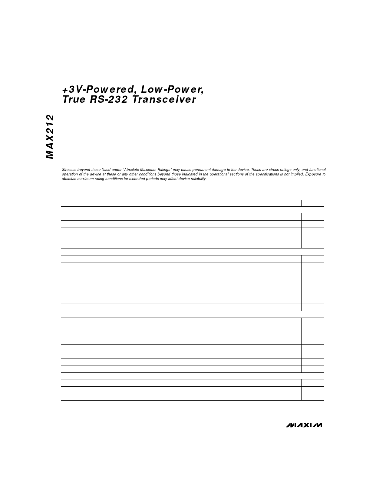
Stresses beyond those listed under “Absolute Maximum Ratings” may cause permanent damage to the device. These are stress ratings only, and functional
operation of the device at these or any other conditions beyond those indicated in the operational sections of the specifications is not implied. Exposure to
absolute maximum rating conditions for extended periods may affect device reliability.
ELECTRICAL CHARACTERISTICS
(VCC = 3.0V to 3.6V, TA = TMIN to TMAX, unless otherwise noted.)
PARAMETER
DC CHARACTERISTICS
Operating Voltage Range
VCC Supply Current
Shutdown Supply Current
Shutdown Supply Current with
Receivers Active
LOGIC
Input Logic Threshold Low
Input Logic Threshold High
Input Current High
Input Current Low
Hysteresis
Logic Output Voltage Low
Logic Output Voltage High
Logic Output Leakage Current
EIA/TIA-232E RECEIVERS
EIA/TIA-232E Input Voltage
Operating Range
CONDITIONS
Meets or exceeds EIA/TIA-232E specifications
No load, VCC = 3.3V
S–—D = EN = GND, R_IN = GND or VCC
–—
SD = GND, EN = VCC, R_IN = GND or VCC
T_IN, EN, S–—D; VCC = 3.0V to 3.6V
T_IN, EN, S–—D; VCC = 3.0V to 3.6V
T_IN, EN, S–—D; VIN = VCC
T_IN, EN, S–—D, VIN = GND
T_IN; VCC = 3.3V
IOUT = 1.0mA
IOUT = -1.0mA
EN = GND, 0V < R_OUT < VCC
MIN TYP MAX UNITS
3.0
3.6
V
1.5
3.0
mA
1
15
µA
1
15
µA
2VCC / 3
VCC / 3
V
V
1
µA
1
µA
0.3
V
0.25
V
VCC - 0.5
V
±10
µA
-25
+25
V
EIA/TIA-232E Input Voltage
Threshold Low
0.4
V
EIA/TIA-232E Input Voltage
Threshold High
EIA/TIA-232E Input Hysteresis
EIA/TIA-232E Input Resistance
EIA/TIA-232E TRANSMITTERS
Output Voltage Swing (VHIGH, VLOW)
Output Resistance
EIA/TIA-232E Short-Circuit Current
-15V < VIN < 15V
All transmitters loaded 3kΩ to GND
VCC = V- = V+ = 0V, -2V < T_OUT < 2V
2.8
V
0.7
V
3
5
7
kΩ
±5.0 ±5.5
V
300
Ω
28
100
mA
2 _______________________________________________________________________________________
Share Link: 