MAX212C/D 데이터 시트보기 (PDF) - Maxim Integrated
부품명
상세내역
제조사
MAX212C/D Datasheet PDF : 8 Pages
| |||
+3V-Powered, Low-Power,
True RS-232 Transceiver
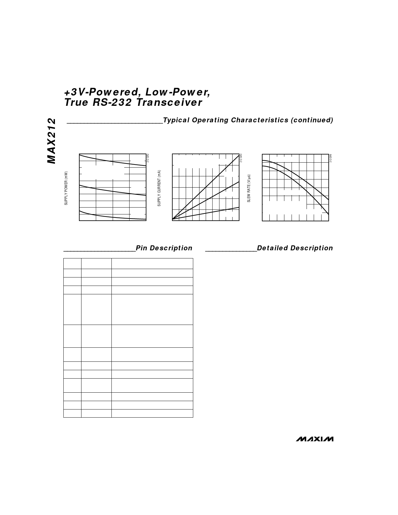
____________________________Typical Operating Characteristics (continued)
(VCC = 3.3V, TA = +25°C, unless otherwise noted.)
SUPPLY POWER vs.
SUPPLY VOLTAGE
180
120kbps
160 ALL TRANSMITTERS
AT SPECIFIED DATA RATES
w/ 2500pF AND 3kΩ LOADS
140
64kbps
120
100
80
2.5
20kbps
3.0
3.5
4.0
4.5
SUPPLY VOLTAGE (V)
SUPPLY CURRENT vs.
LOAD CAPACITANCE
80
ALL TRANSMITTERS
AT SPECIFIED CAPACITANCE AND
70 DATA RATES w/ 3kΩ LOADS
60
120kbps
50
64kbps
40
30
20
0
20kbps
1000 2000 3000 4000 5000
LOAD CAPACITANCE (pF)
SLEW RATE vs.
LOAD CAPACITANCE
14
RISING EDGE
13
12
11
10
FALLING EDGE
9
8 ALL TRANSMITTERS
LOADED SIMULTANEOUSLY
7 w/ SPECIFIED CAPACITANCE AND 3kΩ
6
500
1500
2500 3500 4500
LOAD CAPACITANCE (pF)
_____________________Pin Description
PIN
NAME
1
LN
2
LP
3
VCC
4
S–—D
5
EN
6-10
11-13
14
15-17
18-22
23
24
R1OUT-
R5OUT
T1IN-T3IN
V-
T3OUT-
T1OUT
R5IN-R1IN
V+
GND
FUNCTION
Inductor/Diode Connection Point
Inductor/Diode Connection Point
Supply Voltage Input, 3.0V to 3.6V
Shutdown Control. Connect to VCC
for normal operation. Connect to
GND to shut down the power supply
and to disable the drivers. Receiver
status is not changed by this control.
Receiver Enable Control. Connect
to VCC for normal operation.
Connect to GND to force the
receiver outputs into a high-Z state.
Receiver Outputs, swing GND
to VCC
Transmitter Inputs
Negative Supply generated on-board
Transmitter Outputs
Receiver Inputs
Positive Supply generated on-board
Ground
_______________Detailed Description
The MAX212 line driver/receiver is intended for 3V-
powered EIA/TIA-232E and V.28/V.24 communications
interfaces where 3 drivers and 5 receivers are
required. The operating voltage range extends from
3.6V down to 3.0V while still maintaining true RS-232
and EIA/TIA-562 transmitter output voltage levels.
The circuit comprises three sections: power supply,
transmitters, and receivers. The power-supply sec-
tion converts the supplied 3V to about ±6.5V, to pro-
vide the voltages necessary for the drivers to meet
true RS-232 levels. External components are small
and inexpensive.
The transmitters and receivers are guaranteed to oper-
ate at data rates of 120kbps.
A shutdown mode reduces current to 1µA to extend
battery life in portable systems. While shut down, all
receivers can remain active or can be disabled under
logic control. This enables a system incorporating the
MAX212 to be in low-power shutdown mode and still
monitor incoming RS-232 activity.
Three-state drivers on all receiver outputs are provided
so that multiple receivers, generally of different inter-
face standards, can be wire-ORed at the UART.
4 _______________________________________________________________________________________
Share Link: 