MAX3510 데이터 시트보기 (PDF) - Maxim Integrated
부품명
상세내역
제조사
MAX3510 Datasheet PDF : 12 Pages
| |||
Upstream CATV Amplifier
Ramp Generator
The ramp generator circuit is a simple RC charging cir-
cuit, which is used to control power-up and power-down
of the output power amplifier. It is made up of CEXT1
and an internal 2kΩ resistor. The choice of CEXT1 is gov-
erned by the period of the burst on/off cycle. CEXT1
must be small enough to fully charge/discharge within a
burst. A typical value of CEXT1 is 0.0033µF.
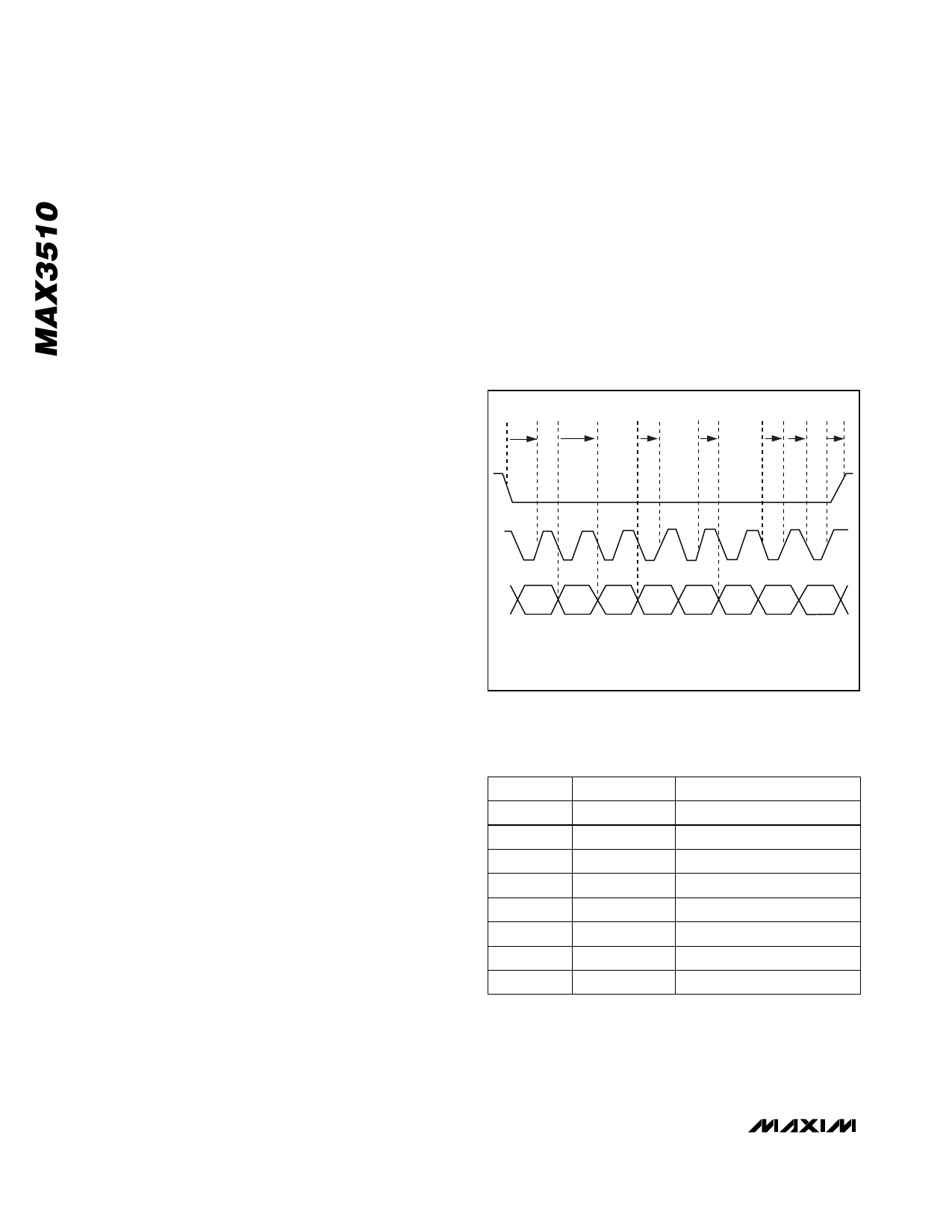
Serial Interface
The serial interface has an active-low enable (CS) to
bracket the data, with data clocked in MSB first on the
rising edge of SCLK. Data is stored in the storage latch
on the rising edge of CS. The serial interface controls the
state of the PGA. Tables 2 and 3 show the register for-
mat. Serial-interface timing is shown in Figure 2.
PGA Bias Cell
The PGA bias cell is accessed by the SHDN pin. When
this pin is taken low, the programmable-gain amplifier
and serial data interface are shut off. Note that any gain
setting stored in the serial data interface latch will be
lost. The power amplifier is unaffected by the PGA Bias
cell, therefore TXEN must be held low to be in shut-
down mode. This mode lowers supply current draw to
less than 1µA typical.
Power Amp Bias Cell
The power amp bias cell is used to enable and disable
bias to the output differential pair. This is controlled by
the TXEN pin (18).
Functional Modes
The MAX3510 has four functional modes controlled
through the serial interface or external pins (Table 3):
transmit mode, transmit-disable mode, software-shut-
down mode, and shutdown mode.
Transmit Mode
Transmit mode is the normal active mode of the
MAX3510. The TXEN pin must be held high in this
mode. Note that SHDN must also be held high.
Transmit-Disable Mode
When in transmit-disable mode, the power amplifier is
completely shut off. This mode is activated by taking
TXEN low while keeping SHDN high. This mode is typi-
cally used between bursts in TDMA systems. Transients
are controlled by the action of the transformer balance.
Software-Shutdown Mode
Software-shutdown mode is enabled when D7 = 0 and
TXEN is low. This mode minimizes current consumption
while maintaining the programmed gain state stored in
the latch of the serial-data interface. All analog func-
tions are disabled in this mode and current consump-
tion is reduced to under 2mA.
Shutdown Mode
In normal operation the shutdown pin (SHDN) is held
high. When SHDN and TXEN are taken low, all circuits
within the IC are disabled. Only leakage currents flow in
this state. Data stored within the serial-data interface
latches will be lost upon entering this mode. Current
draw is reduced to 1µA (typ) in shutdown mode.
A
G
B
C
DE
F
D7
D6
D5
D4
D3
D2
D1
D0
A. tSENS
B. tSDAS
C. tSDAH
D. tSCLKL
E. tSCLKH
F. tSENH
G. tDATAH/tDATAL
Figure 2. Serial-Interface Timing Diagram
Table 2. Serial-Interface Control Word
BIT
MSB 7
MNEMONIC
D7
DESCRIPTION
Software Shutdown
6
D6
Test Bit
5
D5
Gain Control, Bit 5
4
D4
Gain Control, Bit 4
3
D3
Gain Control, Bit 3
2
D2
Gain Control, Bit 2
1
LSB 0
D1
Gain Control, Bit 1
D0
Gain Control, Bit 0
8 _______________________________________________________________________________________
Share Link: 