MAX3815A 데이터 시트보기 (PDF) - Maxim Integrated
부품명
상세내역
제조사
MAX3815A Datasheet PDF : 11 Pages
| |||
TMDS Digital Video Equalizer for
HDMI/DVI Cables
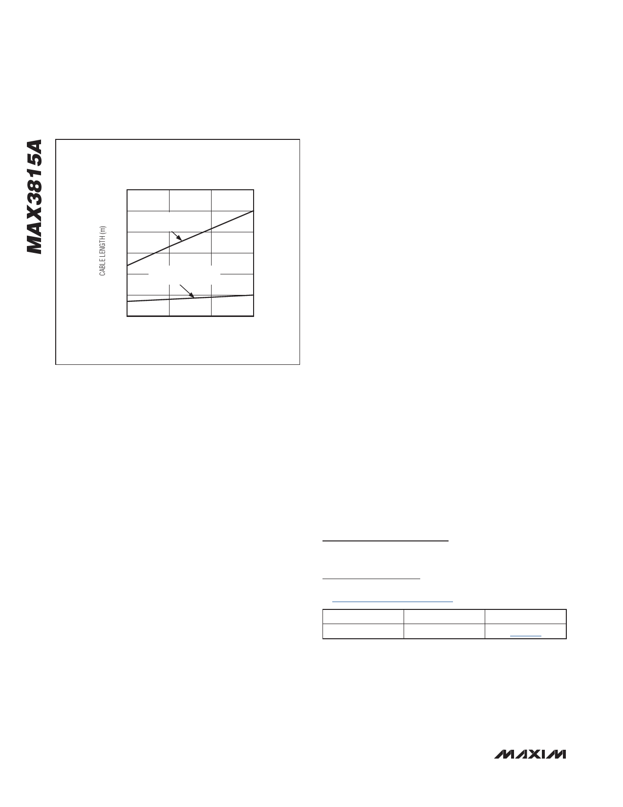
TYPICAL MAX3815A CABLE REACH
(DATA RATE = 2.25Gbps)
60
50
TYPICAL LIMIT OF CABLE
WITH EQ AT 2.25Gbps
40
30
20
TYPICAL LIMIT OF CABLE
WITHOUT EQ AT 2.25Gbps
10
0
28
26
24
22
WIRE GAUGE (AWG)
Figure 7. Cable Reach
Output On (OUTON) Input
The OUTON pin is an LVTTL input. Force the pin low to
enable the outputs. Force the pin high to set a differen-
tial zero on the outputs, irrespective of the signal at the
inputs.
Cable Selection
TMDS performance is heavily dependent on cable quality.
Deterministic jitter (DJ) can be caused by differential-to-
common-mode conversion (or vice versa) within a twisted
pair (STP or UTP), usually a result of cable twist or dielectric
imbalance. Refer to Application Note 3353: HFAN-04.5.4:
‘Jitter Happens’ when a Twisted Pair is Unbalanced and
Application Note 4218: Unbalanced Twisted Pairs Can
Give You the Jitters! for more information.
Layout Considerations
The data and clock inputs are the most critical paths for
the MAX3815A and great care should be taken to mini-
mize discontinuities on these transmission lines between
the connector and the IC. Here are some suggestions for
maximizing the performance of the MAX3815A:
• The data and clock inputs should be wired directly
between the cable connector and IC without stubs.
• Place supply filter capacitors close to the MAX3815A
inputs to provide a low inductance path for supply
return currents.
• Input and output data channel designations are only
a guide. Polarity assignments can be swapped and
channel paths can be interchanged.
• An uninterrupted ground plane should be positioned
beneath the high-speed I/Os.
• Ground-path vias should be placed close to the input/
output connectors to allow a low inductance return
current path.
• Maintain 100Ω differential transmission line impedance
into and out of the MAX3815A.
• Use good high-frequency layout techniques and
multilayer boards with an uninterrupted ground plane
to minimize EMI and crosstalk. Refer to Application
Note 3854: MAX3815: Interfacing to the MAX3815
DVI/HDMI Cable Equalizer and the EV kit data sheet,
MAX3815AEVKIT-HDMI.
Exposed-Pad Package
The exposed pad on the 48-pin TQFP-EP provides a very
low thermal resistance path for heat removal from the
IC. The pad is also electrical ground on the MAX3815A
and must be soldered to the circuit board ground
for proper thermal and electrical performance. Refer
to Maxim Application Note 862: HFAN-08.1: Thermal
Considerations of QFN and Other Exposed-Paddle
Packages for additional information.
Chip Information
PROCESS: SiGe BiPOLAR
Package Information
For the latest package outline information and land patterns, go
to www.maxim-ic.com/packages.
PACKAGE TYPE PACKAGE CODE DOCUMENT NO.
48 TQFP-EP
C48E+8
21-0065
10 �������������������������������������������������������������������������������������
Share Link: 