MAX4032 데이터 시트보기 (PDF) - Maxim Integrated
부품명
상세내역
제조사
MAX4032
Maxim Integrated

MAX4032 Datasheet PDF : 10 Pages
| |||
5V, 6dB Video Buffer with Sync-Tip Clamp,
Output Sag Correction, and 150nA Shutdown Current
Detailed Description
The MAX4032 5V, 6dB video buffer with sync-tip
clamp, output sag correction, and low-power shutdown
mode is available in tiny SOT23 and SC70 packages.
The sag-corrected output of the MAX4032 is designed
to drive AC-coupled, 150Ω back-terminated video
loads in portable video applications such as digital still
cams, portable DVD players, digital camcorders,
PDAs, video-enabled cell phones, portable game sys-
tems, and notebook computers. The sag correction
feature introduces low-frequency compensation that
reduces the value of the normally bulky and expensive
330µF AC-coupling capacitor to two small, less expen-
sive 22µF capacitors. The input clamp positions the
video waveform at the output and allows the MAX4032
to be used as either an AC- or DC-coupled output driver.
The MAX4032 operates from a single 5V supply and
consumes only 6.5mA of supply current. The low-power
shutdown mode reduces the supply current to 150nA,
making the MAX4032 ideal for low-voltage, battery-
powered video applications.
The input signal to the MAX4032 is AC-coupled through
a capacitor into an active sync-tip clamp circuit, which
places the minimum of the video signal at approximate-
ly 0.38V. The output buffer amplifies the video signal
while still maintaining the 0.38V clamp voltage at the
output. For example, if VIN = 0.38V, then VOUT = 0.38V.
If VIN = (0.38V + 1V) = 1.38V, then VOUT = (0.38V + 2 X
(1V)) = 2.38V when SAG is shorted OUT.
There are two common output connections for the
MAX4032:
1) SAG is shorted to OUT and 150Ω is directly con-
nected from OUT to ground (see Figure 2).
2) Two capacitors and 150Ω are connected between
OUT, SAG, and ground (see Figure 3).
Sag Correction
Sag correction refers to the low-frequency compensa-
tion of the highpass filter formed by the 150Ω load of a
back-terminated coax and the output-coupling capaci-
tor. This break point must be low enough in frequency
to pass the Vertical Sync Interval (<25Hz for PAL and
<30Hz for NTSC) to avoid Field Tilt. Traditionally, the
break point is made <3~5Hz, and the coupling capaci-
tor must be very large, typically >330µF. The MAX4032
reduces the value of this coupling capacitor, replacing
it with a pair of 22µF capacitors. This is done by putting
a resistor network in series with the feedback, raising
the gain, and creating a high-impedance node at the
SAG output. This node is AC-coupled to the load in par-
allel with the normal output, as shown in Figure 3. This
allows the use of two smaller capacitors (COUT and
CSAG), typically 22µF, substantially reducing the size of
the interface caps and their cost while retaining the low-
frequency response.
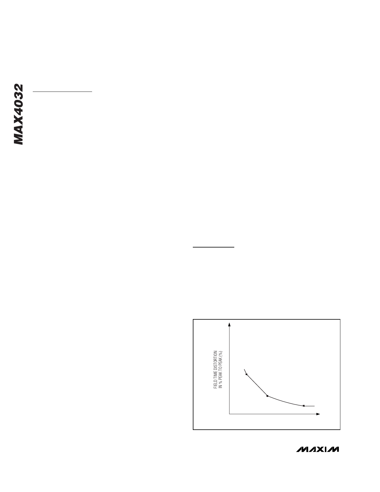
The minimum value of the output-coupling capacitor is
a function of the acceptable Field Tilt. In Figure 1, the
Field Tilt is given for several values of capacitance from
10µF to 47µF for comparison. Although values lower
than 22µF may have acceptable Field Tilt, they are not
recommended, since tolerance, aging, and voltage
and temperature coefficients reduce the capacitance in
actual applications. Increasing the output-
coupling capacitors beyond 47µF does not improve
performance.
Shutdown Mode
The MAX4032 features a low-power shutdown mode
(ISHDN = 150nA) for battery-powered/portable applica-
tions. Pulling the SHDN pin high enables the output.
Connecting the SHDN pin to ground (GND) disables
the output and places the MAX4032 into a low-power
shutdown mode.
Applications Information
Input Coupling the MAX4032
The MAX4032 input must be AC-coupled because the
input capacitor stores the clamp voltage. The MAX4032
requires a typical value of 0.1µF for the input clamp to
meet the Line Droop specification. A minimum of a
ceramic capacitor with an X7R temperature coefficient is
recommended to avoid temperature-related problems
with Line Droop. For extended temperature operation,
such as outdoor applications, or where the impressed
100
80
60
40
20
10
20
30
40
50
COUPLING CAPACITANCE (µF)
Figure 1. Field Tilt vs. Output-Coupling Capacitance
6 _______________________________________________________________________________________
Share Link: