MAX7462 데이터 시트보기 (PDF) - Maxim Integrated
부품명
상세내역
제조사
MAX7462 Datasheet PDF : 8 Pages
| |||
Single-Channel Video Reconstruction Filters
and Buffers
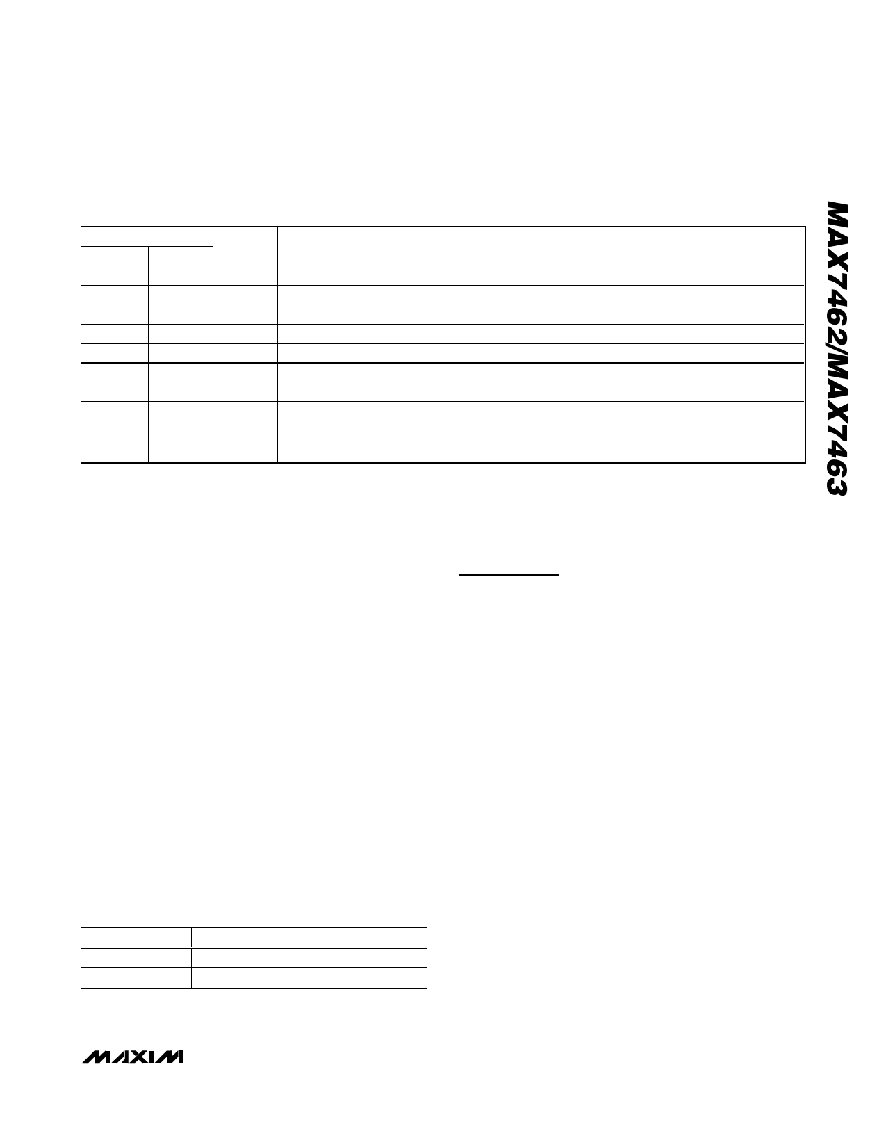
Pin Description
PIN
MAX7462 MAX7463
1
1
NAME
IN
FUNCTION
Video Input. AC-couple IN with a series 0.1µF capacitor.
2
—
GAIN Gain Control Input. Connect GAIN to GND for a gain of +6dB (+2V/V). Connect GAIN to VCC
for a gain of +9.5dB (+3V/V).
3, 4, 5
—
3
2, 4, 5, 6
GND
N.C.
Ground
No Connection. Not internally connected. Connect to GND for better performance.
6
—
DISABLE Disable Input. Connect to VCC to enable the output buffer (normal operation). Connect to GND
to put the output buffer in a high-impedance state.
7
7
VCC +5V Supply Input
8
8
OUT
Buffer Output. This output can be either AC- or DC-coupled. Use at minimum a 220µF
capacitor for AC-coupled loads.
Detailed Description
The MAX7462/MAX7463 filters and buffers the analog
CVBS video outputs of DAC video-encoders in applica-
tions such as set-top boxes, hard-disk recorders, DVD
players, and digital VCRs. The MAX7462/MAX7463 con-
sist of a lowpass filter and an output video buffer that can
drive two standard 150Ω video loads. These devices
operate from a single +5V supply and have a bandwidth
optimized for interlaced NTSC, PAL, and SDTV.
Filter
The reconstruction filter is a 4th-order Butterworth-type
response that features a maximally flat passband for
NTSC and PAL bandwidths. The stopband attenuation
is optimized for a video-encoder DAC sampling fre-
quency of 27MHz (see the Typical Operating
Characteristics).
Output Buffer
The output buffer can drive two 150Ω video loads with
a 2VP-P signal. For the MAX7462, the output buffer gain
is selectable between +6dB and +9.5dB by using GAIN
(see Table 1). The MAX7463 has a fixed gain of +6dB.
The MAX7462/MAX7463 can drive an AC load or drive
the video load directly without using a large output
Table 1. Gain Setting Control (MAX7462)
GAIN
GND
VCC
BUFFER GAIN (dB)
+6
+9.5
capacitor. The output buffer can drive DC loads while
maintaining an output blanking level of less than 1V. The
blanking level allows the MAX7462/MAX7463 to meet the
digital TV interface specifications for DC coupling.
Applications Information
Input Considerations
Use a 0.1µF ceramic capacitor to AC-couple the input.
The input capacitor stores a DC voltage so that the out-
put is clamped to the appropriate DC voltage level.
Output Considerations
The outputs are typically connected to a 75Ω series
back-match resistor followed by the video cable.
Because of the inherent divide-by-two of this configura-
tion, the blanking level on the video cable is always
less than 1V, complying with industry-standard video
requirements such as the digital TV standard (which
allows up to 1VDC on the video cable) and the
European SCART standard (which allows up to 2VDC
on the video cable). The video buffer can also drive an
AC-coupled video load. Good video performance is
achieved with an output capacitor as low as 220µF.
Power-Supply Bypassing and Layout
The MAX7462/MAX7463 operate from a single +5V
supply. Bypass VCC to GND with a 0.1µF capacitor. In
addition, it is sometimes advantageous to connect a
10µF capacitor within the general vicinity of the video
circuitry. Place all other external components as close
to the device as possible.
_______________________________________________________________________________________ 5
Share Link: 