MAX9949FCCB 데이터 시트보기 (PDF) - Maxim Integrated
부품명
상세내역
제조사
MAX9949FCCB Datasheet PDF : 23 Pages
| |||
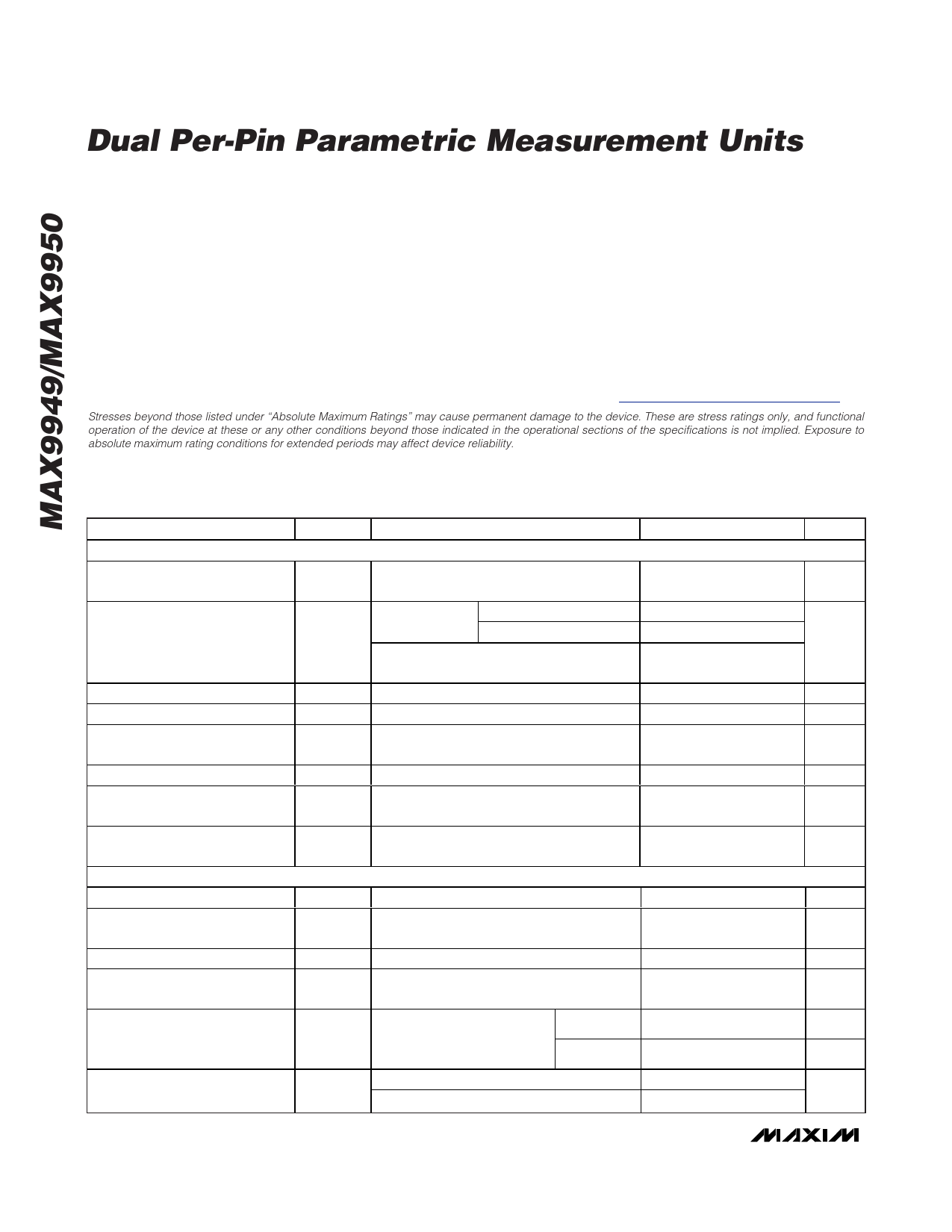
Dual Per-Pin Parametric Measurement Units
ABSOLUTE MAXIMUM RATINGS
VCC to AGND .......................................................................+20V
VEE to AGND.........................................................................-15V
VCC to VEE ...........................................................................+32V
VL to AGND............................................................................+6V
AGND to DGND.....................................................-0.5V to +0.5V
All Other Pins ...................................(VEE - 0.3V) to (VCC + 0.3V)
Digital Inputs/Outputs ......-0.3V to (VL + 0.3V)Continuous Power
Dissipation (TA = +70°C)
64-Pin TQFP-EP (derate 43.5mW/°C above +70°C)....3478mW
θJA (Note 1) ................................................................+23.0°C/W
θJC (Note 1) .....................................................................+8°C/W
Junction Temperature ......................................................+150°C
Storage Temperature Range .............................-65°C to +150°C
Operating Temperature (commercial) Range ........0°C to +70°C
Lead Temperature (soldering, 10s) .................................+300°C
Soldering Temperature (reflow) .......................................+260°C
Note 1: Package thermal resistances were obtained using the method described in JEDEC specification JESD51-7, using a four-
layer board. For detailed information on package thermal considerations, refer to www.maxim-ic.com/thermal-tutorial.
Stresses beyond those listed under “Absolute Maximum Ratings” may cause permanent damage to the device. These are stress ratings only, and functional
operation of the device at these or any other conditions beyond those indicated in the operational sections of the specifications is not implied. Exposure to
absolute maximum rating conditions for extended periods may affect device reliability.
DC ELECTRICAL CHARACTERISTICS
(VCC = +12V, VEE = -7V, VL = +3.3V, TA = TMIN to TMAX, unless otherwise noted. TA < +25°C guaranteed by design and characterization.
Typical values are at TA = +25°C, unless otherwise specified.) (Note 2)
PARAMETER
SYMBOL
CONDITIONS
MIN TYP MAX UNITS
FORCE VOLTAGE (Note 3)
Force Input Voltage Range
VIN0_,
VIN1_
VEE +
3.5V
VCC -
3.5V
V
Forced Voltage
VDUT
DUT current at VCC = +12V, VEE = -7V
full scale
VCC = +18V, VEE = -12V
DUT current = 0A
-2
-7
VEE +
3.5V
+7
+13
V
VCC -
3.5V
Input Bias Current
±1
µA
Forced-Voltage Offset Error
VFOS TA = +25°C
-25
+25
mV
Forced-Voltage Offset
Temperature Coefficient
±100
µV/°C
Forced-Voltage Gain Error
VFGE TA = +25°C, nominal gain of +1
-1 0.005 +1
%
Forced-Voltage Gain
Temperature Coefficient
±10
ppm/°C
Forced-Voltage Linearity Error
MEASURE CURRENT (Note 3)
Measure-Current Offset
Measure-Current Offset
Temperature Coefficient
Measure-Current Gain Error
Measure-Current Gain
Temperature Coefficient
VFLER
TA = +25°C, gain and offset errors
calibrated out (Notes 4, 5)
IMOS TA = +25°C (Note 4)
IMGE TA = +25°C (Note 7)
-0.02
+0.02 %FSR
-1
+1 %FSR
±20
ppm/°C
-1
+1
%
±20
ppm/°C
Linearity Error
IMLER
TA = +25°C, gain, offset, and Ranges A–D
common-mode errors
calibrated out (Notes 4, 5, 6) Range E
-0.02
-1
+0.02
+1
%FSR
nA
Measure Output Voltage Range
over Full Current Range (Note 8)
VMSR
VIOS = VDUTGND
VIOS = 4V + VDUTGND
-4
+4
V
0
8
2 _______________________________________________________________________________________
Share Link: 