MC145017(2005) 데이터 시트보기 (PDF) - Freescale Semiconductor
부품명
상세내역
제조사
MC145017
(Rev.:2005)
(Rev.:2005)
Freescale Semiconductor

MC145017 Datasheet PDF : 8 Pages
| |||
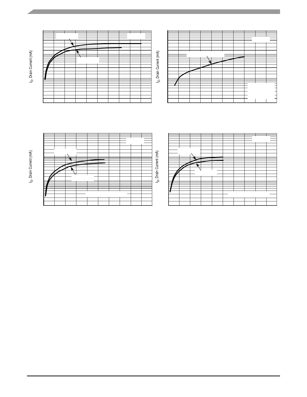
100.0
10.0
VDD = 9.0 Vdc
VDD = 7.2 Vdc
10.0
TA = 25°C
1.0
VDD = 9.0 Vdc or 7.2 Vdc
TA = 25°C
1.0
0.1
0 1 2 3 4 5 6 7 8 9 10
VDS, Drain To Source Voltage (Vdc)
Figure 3. Typical LED Output I–V Characteristic
0.1
P-CH Source
And N-CH Sink
Current
0.01
0 1 2 3 4 5 6 7 8 9 10
VDS, Drain To Source Voltage (Vdc)
Figure 4. Typical Comparator Output I–V Characteristic
1000.0
100.0
VDD = 9.0 Vdc
TA = 25°C
1000.0
100.0
VDD = 9.0 Vdc
TA = 25°C
10.0
VDD = 7.2 Vdc
VDD = 7.2 Vdc
10.0
P-CH Source Current
N-CH Sink Current
1.0
1.0
0 1 2 3 4 5 6 7 8 9 10
0 1 2 3 4 5 6 7 8 9 10
VDS, Drain To Source Voltage (Vdc)
VDS, Drain To Source Voltage (Vdc)
Figure 5. Typical P Horn Driver Output I–V Characteristic
DEVICE OPERATION
Timing
The internal oscillator of the MC145017 operates with a
period of 1.65 seconds during no-smoke conditions. Each
1.65 seconds, internal power is applied to the entire IC and a
check is made for smoke, except during LED pulse, Low
Battery Alarm Chirp, or Horn Modulation (in smoke). Every 24
clock cycles a check is made for low battery by comparing
VDD to an internal zener voltage. Since very small currents
are used in the oscillator, the oscillator capacitor should be of
a low leakage type.
Detect Circuitry
If smoke is detected, the oscillator period becomes
41.67 ms and the piezoelectric horn oscillator circuit is
enabled. The horn output is modulated 500 ms on, 500 ms
off. During the off time, smoke is again checked and will
inhibit further horn output if no smoke is sensed. During
smoke conditions the low battery alarm is inhibited, but the
LED pulses at a 1.0 Hz rate.
An active guard is provided on both pins adjacent to the
detect input. The voltage at these pins will be within 100 mV
of the input signal. This will keep surface leakage currents to
a minimum and provide a method of measuring the input
voltage without loading the ionization chamber. The active
guard op amp is not power strobed and thus gives constant
protection from surface leakage currents. Pin 15 (the Detect
input) has internal diode protection against static damage.
Sensitivity/Low Battery Thresholds
Both the sensitivity threshold and the low battery voltage
levels are set internally by a common voltage divider (please
see Figure 2) connected between VDD and VSS. These
voltages can be altered by external resistors connected from
pins 3 or 13 to either VDD or VSS. There will be a slight
interaction here due to the common voltage divider network.
The sensitivity threshold can also be set by adjusting the
smoke chamber ionization source.
Test Mode
Since the internal op amps and comparators are power
strobed, adjustments for sensitivity or low battery level could
be difficult and/or time-consuming. By forcing Pin 12 to VSS,
the power strobing is bypassed and the outputs, Pins 1 and
4, constantly show smoke/no smoke and good battery/low
MC145017
4
Sensors
Freescale Semiconductor
Share Link: