MCZ145017EG/R2 데이터 시트보기 (PDF) - Freescale Semiconductor
부품명
상세내역
제조사
MCZ145017EG/R2
Freescale Semiconductor

MCZ145017EG/R2 Datasheet PDF : 10 Pages
| |||
battery, respectively. Pin 1 = VDD for smoke and Pin 4 = VDD
for low battery. In this mode and during the 10 ms power
strobe, chip current rises to approximately 50 µA.
Led Pulse
The 9-volt battery level is checked every 40 seconds
during the LED pulse. The battery is loaded via a 10 mA
pulse for 11.6 ms. If the LED is not used, it should be replaced
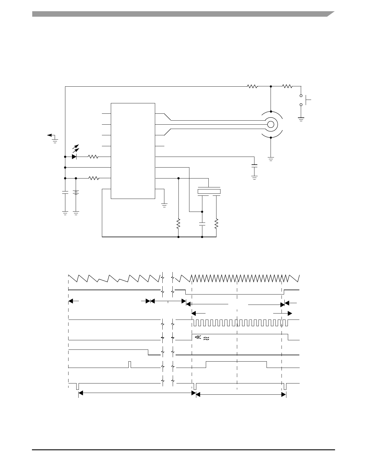
0.1 µF
330 Ω
8.2 MΩ
+
9V
1
16
MC145017
2
15
3
14
4
13
5
12
6
11
7
10
8
9
with an equivalent resistor such that the battery loading
remains at 10 mA.
Hysteresis
When smoke is detected, the resistor/divider network that
sets sensitivity is altered to increase sensitivity. This yields
approximately 100 mV of hysteresis and reduces false
triggering.
1M
1M
Test
0.1 µF
0.001 µF
1.5 MΩ*
220 kΩ*
*NOTE: Component values may change depending on type of piezoelectric horn used.
Figure 6. Typical Application as Ionization Smoke Detector
OSC
Pin 12
Smoke - N
-Y
Low Bat - Y
-N
HYST
Pin 13
1 23 45 67 8 9
23 24 1
6
12
18
No Smoke, Low Battery
No Smk
No Low Bat
Smoke
Latch Alarm Condition
( 100 mV Level Shift)
24
OSC
Pin 12
Smoke - N
-Y
No Smk
LOW BAT - Y
-N
HORN - On LOW BATTERY CHIRP >>
- Off
NFPA MOD >>
(Note 1)
LED - Off
- On
24 Clocks
24 Clocks
NOTES:
1. Horn modulation is self-completing. When going from smoke to no smoke, the alarm condition will terminate only when horn is off.
2. Comparators are strobed once per cycle (1.65 sec for no smoke, 40 msec for smoke).
Figure 7. MC145017 Timing Diagram
Sensors
Freescale Semiconductor
HORN - ON
- OFF
LED - OFF
- ON
MC145017
5
Share Link: