MCRF450 데이터 시트보기 (PDF) - Microchip Technology
부품명
상세내역
제조사
MCRF450 Datasheet PDF : 50 Pages
| |||
MCRF450/451/452/455
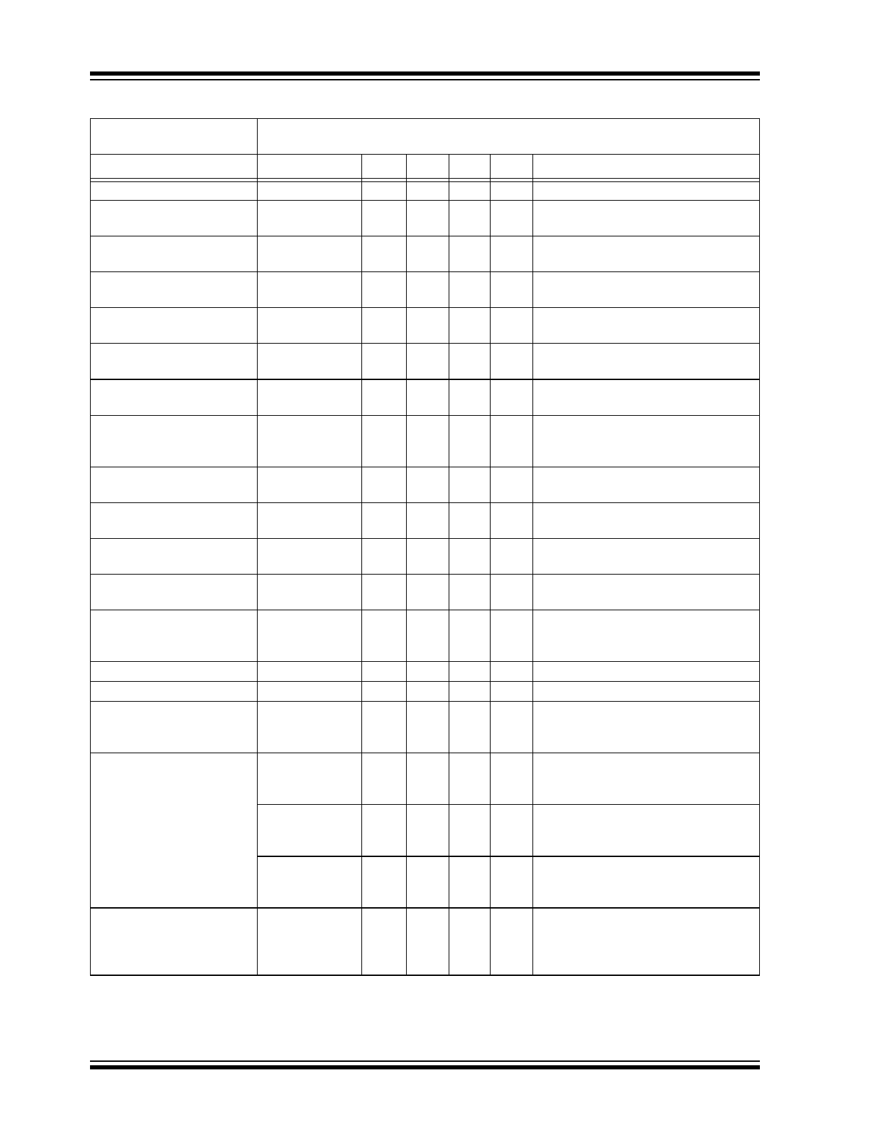
TABLE 2-3:
OPERATING AC CHARACTERISTICS
Standard Operating Conditions (unless otherwise stated)
Operating Temperature = -20°C to +70°C.
Parameters
Symbol
Min Typ Max Units
Conditions
Carrier frequency
Device data rate
FC
2.0 13.56 35
FM
58 70 82
Pulse width of 1-of-16 PPM
for Normal mode
PWPPM_N
145 175 205
Pulse width of 1-of-16 PPM
for Fast mode
PWPPM_F
8.3 10 11.7
Symbol duration of 1-of-
16 PPM for Normal mode
SWPPM_N
2.32 2.8 3.28
Symbol duration of
1-of-16 PPM for Fast mode
SWPPM_F
133 160 187
Modulation index of gap
pulse
MODINDEX_GAP 20 60 100
Gap width of Interrogator
command and data except
Fast mode data
GAPWIDTH_N
20 100 150
Gap width of Fast mode
data
GAPWIDTH_F 6.0 7.0 8.0
Coil voltage during reading
VPP_AC
4.0 — —
Detuning voltage
VDETUNE
3.0 4.0 —
EEPROM (Memory)
Writing Time
Command Decode Time
TWRITE
TDECODE
— 5.0 —
0.97 1.225 1.48
Time slot
Listening Window
Command Duration of Fast
Read command (FRR and
FRB)
TSLOT
TLW
T_CMD_FRR
2.1 2.5 2.93
0.82 1.0 1.17
1.305 1.575 1.845
CRES_100
85.5 95 104.5
Internal Resonant
Capacitor
CRES_2_50
27 30 33
CRES_50
45 50 55
Parasitic Input Capacitance
of MCRF450
CPARA_IN
— 3.5 —
Note 1: Tested in production at VDD = 2.8 VDC and 5.0 VDC.
MHz
kHz
µs
µs
ms
µs
%
µs
µs
VPP
VDC
ms
ms
ms
ms
ms
pF
pF
pF
pF
Manchester coding, both Normal and
Fast modes, 70 kHz ±17% (Note 1)
See Figure 6-2 and Table 6-7,
175 µs ±17%
See Figure 6-2 and Table 6-7
See Figure 6-9
See Figure 6-2
See Figure 6-2 and Table 6-7
See Figure 6-2 and Table 6-7
Peak-to-Peak voltage across the coil
during reading
VDD voltage at which the input voltage
limiting circuit becomes active
Write time for a 32-bit block
Time delay between end of command
symbol and start of the device
response
175 µs/pulse position x 9 pulse
positions = 1.575 ms
Between Ant. A and VSS pads at
13.56 MHz and at 25°C (MCRF451)
See Figure 2-3
Between Ant. A and VSS pads at
13.56 MHz and at 25°C (MCRF452)
See Figure 2-4
Between Ant. A and VSS pads at
13.56 MHz and at 25°C (MCRF455)
See Figure 2-5
Between antenna pad A and VSS, at
13.56 MHz with modulation transistor
off (no external coils). Not tested in
production
DS40232H-page 6
2003 Microchip Technology Inc.
Share Link: 