OR2C04A 데이터 시트보기 (PDF) - Lattice Semiconductor
부품명
상세내역
제조사
OR2C04A Datasheet PDF : 192 Pages
| |||
ORCA Series 2 FPGAs
Data Sheet
January 2002
Programmable Logic Cells (continued)
The LUT ripple mode operation offers standard arith-
metic functions, such as 4-bit adders, subtractors,
adder/subtractors, and counters. In the ORCA
Series 2, there are two new ripple modes available. The
first new mode is a 4 x 1 multiplier, and the second is a
4-bit comparator. These new modes offer the advan-
tages of faster speeds as well as denser logic capabili-
ties.
When the LUT is configured to operate in the memory
mode, a 16 x 2 asynchronous memory fits into an
HLUT. Both the MA and MB modes were available in
previous ORCA architectures, and each mode can be
configured in an HLUT separately. In the Series 2,
there are two new memory modes available. The first is
a 16 x 4 synchronous single-port memory (SSPM), and
the second is a 16 x 2 synchronous dual-port memory
(SDPM). These new modes offer easier implementa-
tion, faster speeds, denser RAMs, and a dual-port
capability that wasn’t previously offered as an option in
the ATT2Cxx/ATT2Txx families.
If the LUT is configured to operate in the ripple mode, it
cannot be used for basic combinatorial logic or memory
functions. In modes other than the ripple, SSPM, and
SDPM modes, combinations of operating modes are
possible. For example, the LUT can be configured as a
16 x 2 RAM in one HLUT and a five-input combinatorial
logic function in the second HLUT. This can be done by
configuring HLUTA in the MA mode and HLUTB in the
F5B mode (or vice versa).
F4A/F4B Mode—Two Four-Input Functions
Each HLUT can be used to implement two four-input
combinatorial functions, but the total number of inputs
into each HLUT cannot exceed five. The two QLUTs
within each HLUT share three inputs. In HLUTA, the
A1, A2, and A3 inputs are shared by QLUT2 and
QLUT3. Similarly, in HLUTB, the B1, B2, and B3 inputs
are shared by QLUT0 and QLUT1. The four outputs are
F0, F1, F2, and F3. The results can be routed to the
D0, D1, D2, and D3 latch/FF inputs or as an output of
the PFU. The use of the LUT for four functions of up to
four inputs each is given in Figure 4.
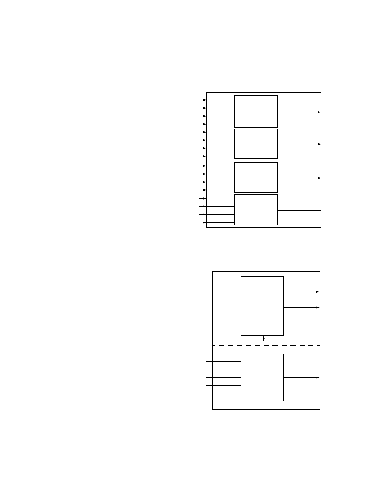
F5A/F5B Mode—One Five-Input Variable Function
Each HLUT can be used to implement any five-input
combinatorial function. The input ports are A[4:0] and
B[4:0], and the output ports are F0 and F3. One five or
less input function is input into A[4:0], and the second
five or less input function is input into B[4:0]. The
results are routed to the latch/FF D0 and latch/FF D3
inputs, or as a PFU output. The use of the LUT for two
8
independent functions of up to five inputs is shown in
Figure 5. In this case, the LUT is configured in the F5A
and F5B modes. As a variation, the LUT can do one
function of up to five input variables and two four-input
functions using F5A and F4B modes or F4A and F5B
modes.
A4
A4
HLUTA
A3
A3
QLUT3
F3
A2
A2
A1
A1
A3
A3
A2
A2
QLUT2
F2
A1
A1
A0
A0
B4
B4
HLUTB
B3
B3
QLUT1
F1
B2
B2
B1
B1
B3
B3
B2
B2
QLUT0
F0
B1
B1
B0
B0
5-2753(F).r2
Figure 4. F4 Mode—Four Functions of Four-
Input Variables
WEA
A3
A2
A1
A0
WD3
WD2
WPE
B4
B3
B2
B1
B0
A4
A3 QLUT3
A2
A1 QLUT2
A0
WD3
WD2 c0
B4
B3 QLUT1
B2
B1 QLUT0
B0
HLUTA
F3
F2
HLUTB
F0
5-2845(F).r2
Figure 5. F5 Mode—Two Functions of Five-Input
Variables
Lattice Semiconductor
Share Link: 