TB2932HQ 데이터 시트보기 (PDF) - Toshiba
부품명
상세내역
제조사
TB2932HQ Datasheet PDF : 37 Pages
| |||
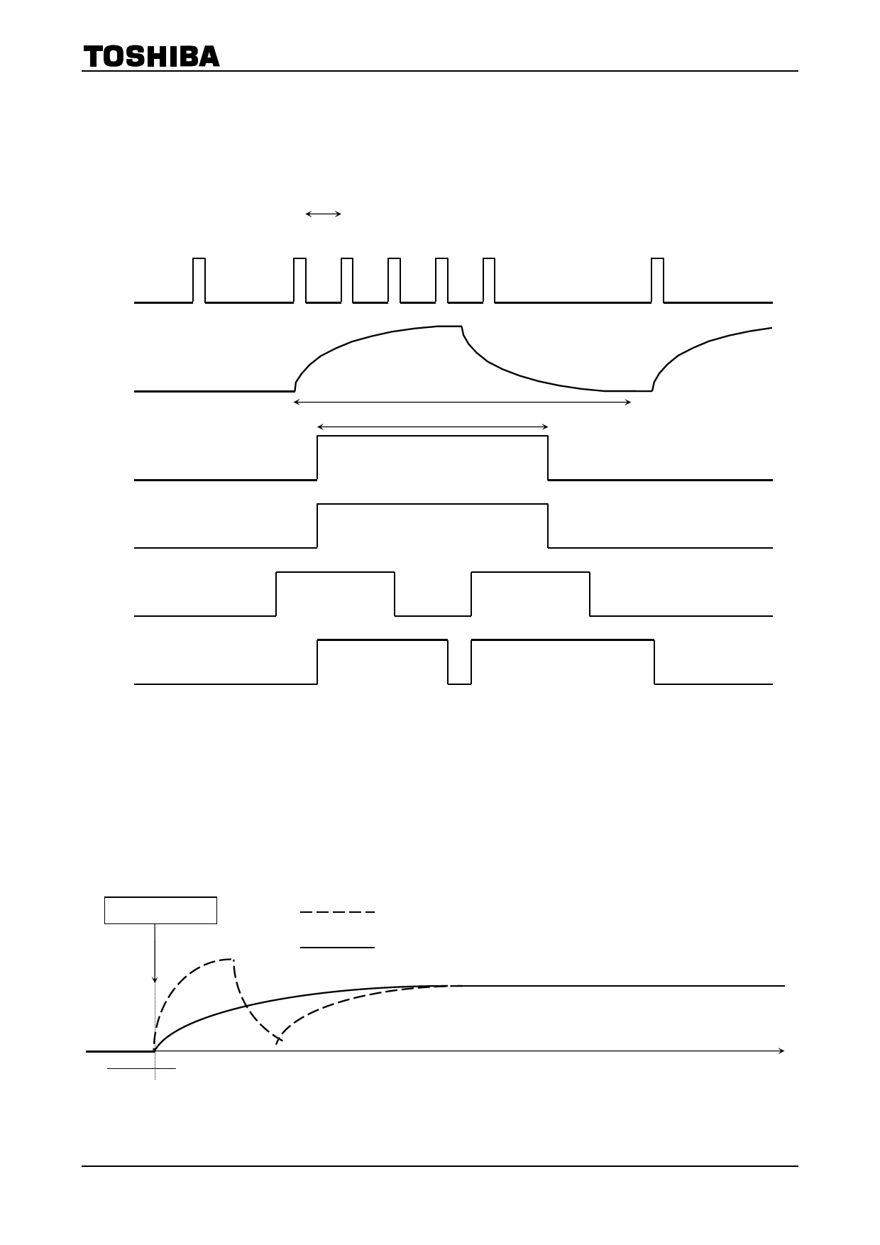
B) Repetition mode
Maximum interval:
You can select the acquisition time.
Minimum interval:
It is determined by the speed of microcomputer.
Writing
(diag cycle enable = 1)
(stand by OFF = 0)
Reading 1
Reading 3
Reading 5
Reading 2
Reading 4
I2C command
TB2932HQ
Reading 6
Pin 10
DB1 D6
(acquisition time with only turn-ON)
Diag enable
About 100 ms
About 80 ms
About 80 ms
Fault event
Latch
The turn ON diagnostic acquisition time is determined by the ripple filter capacitance C2 and
the equivalent internal resistance Rr as below expression.
Acquisition time = 2 × C2 × Rr = 4400 × C2 (typ.)
Rr is fixed in internal circuit and it is not varied by the fluctuation of power supply VCC voltage.
C2 value determines the time from power ON (standby off) to the appearance of sound signal
from output and the characteristic for ripple rejection ratio, too. So, take care with the decision on
C2 value.
If the turn ON diagnosis is not used, in other words the diagnostic cycle defeat command is sent,
the waveform of ripple terminal voltage will change but the time from turning on to the output
signal appearance will not change as illustrated below in Figure4.
WRITE DATA
Pin10
ripple
pin
voltage
Turn ON diagnosis enable
Turn ON diagnosis defeat
Figure 4 Turn on Diagnosis Timing Chart when Turn on diagnosis not used.
10
2009-02-02
Share Link: 