TDA3615J 데이터 시트보기 (PDF) - Philips Electronics
부품명
상세내역
제조사
TDA3615J Datasheet PDF : 18 Pages
| |||
Philips Semiconductors
Multiple voltage regulator
Product specification
TDA3615J
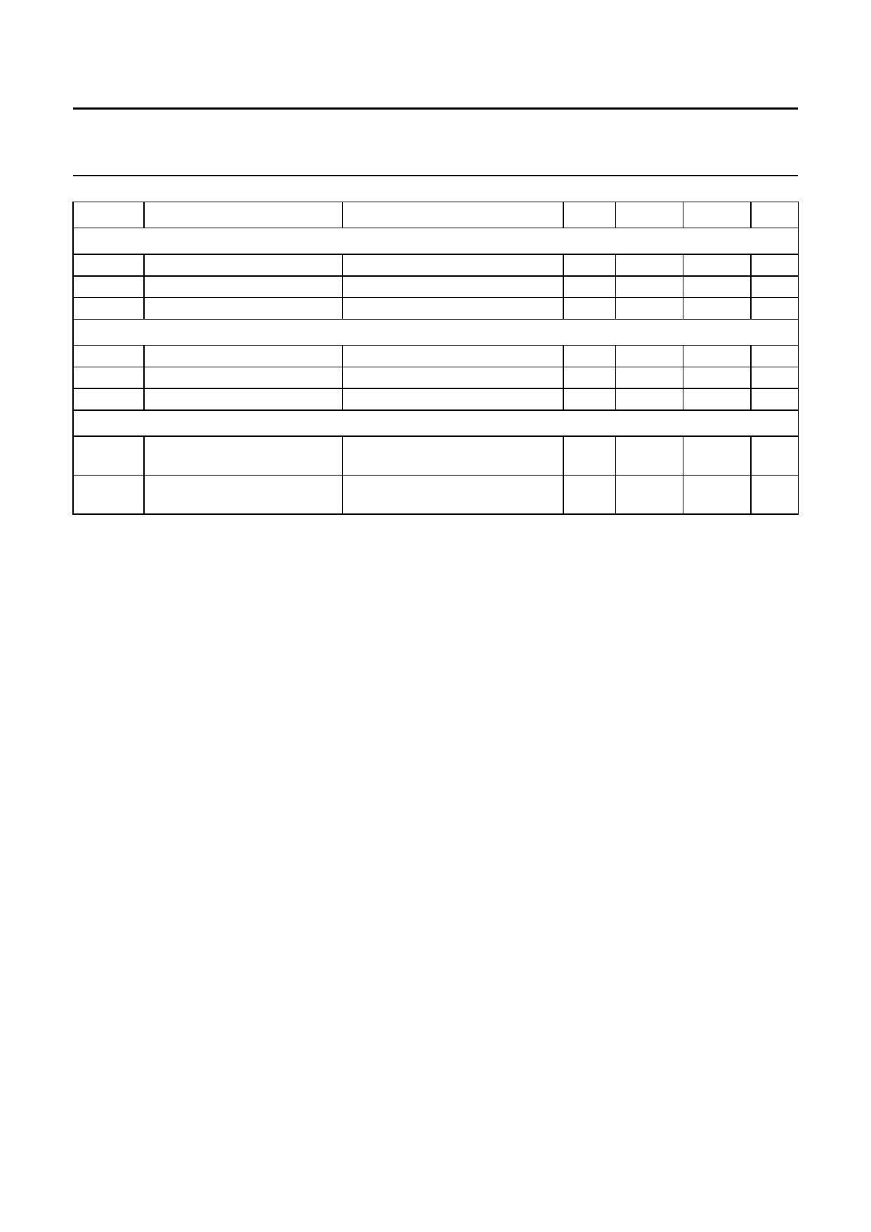
SYMBOL
PARAMETER
CONDITIONS
MIN. TYP. MAX. UNIT
Schmitt trigger 3 for battery sense
Vthr3
Vthf3
Vhys3
rising threshold voltage
falling threshold voltage
hysteresis voltage
Schmitt trigger 4 for ignition sense
Vthr4
Vthf4
Vhys4
rising threshold voltage
falling threshold voltage
hysteresis voltage
Schmitt trigger 5 for load dump
VI(ig) = 14.4 V; RL = 1 kΩ
VI(ig) = 14.4 V; RL = 1 kΩ
Vbat = 14.4 V; RL = 100 Ω
Vbat = 14.4 V; RL = 100 Ω
6.8 7.35
7.9
V
5.5 5.95
6.4
V
−
1.4
−
V
7.2 7.6
8.0
V
6.0 6.3
6.8
V
−
1.3
−
V
Vthr5
Vthf5
rising threshold voltage
falling threshold voltage
selector inputs 1,0,1 (state 8 in
Table 1); note 7
selector inputs 1,0,1 (state 8 in
Table 1); note 7
17.5 18.5
19.5
V
17
Vthr − 0.3 Vthr − 0.1 V
Notes
1. The quiescent current is measured when RL = ∞.
2. Only if Vbat has exceeded 7.2 V.
3. The drop-out voltage of regulator 1 is measured between Vbat and VREGx.
4. The foldback current protection limits the dissipation power at short-circuit.
5. The drop-out voltage of regulators 2 to 6 and power switches 1, 2 and 3 are measured between VI(ig) and VREGx or
between VI(ig) and VSWx.
6. The voltage of regulator 1 sinks as a result of a supply voltage drop.
7. Only when one of the control pins is HIGH.
2004 Jan 12
10
Share Link: 