TISP4350L3 데이터 시트보기 (PDF) - Power Innovations Ltd
부품명
상세내역
제조사
TISP4350L3 Datasheet PDF : 14 Pages
| |||
TISP4070L3BJ, TISP4350L3BJ
BIDIRECTIONAL THYRISTOR OVERVOLTAGE PROTECTORS
AUGUST 1999 — REVISED NOVEMBER 1999
150 V rms a.c., giving a peak voltage of 269 V. The TISP4350L3BJ will not clip the B type ringing voltage as it
has a high impedance up to 275 V.
The TISP4070L3BJ should be connected after the hook switch to protect the following electronics. As the
TISP4070L3BJ has a high impedance up to 58 V, it will switch off after a surge and not be triggered by the
normal exchange battery voltage
These low (L) current protection devices are in a plastic package SMBJ (JEDEC DO-214AA with J-bend
leads) and supplied in embossed tape reel pack. For alternative voltage and holding current values, consult
the factory. For higher rated impulse currents in the SMB package, the 100 A 10/1000 TISP4xxxH3BJ series
is available.
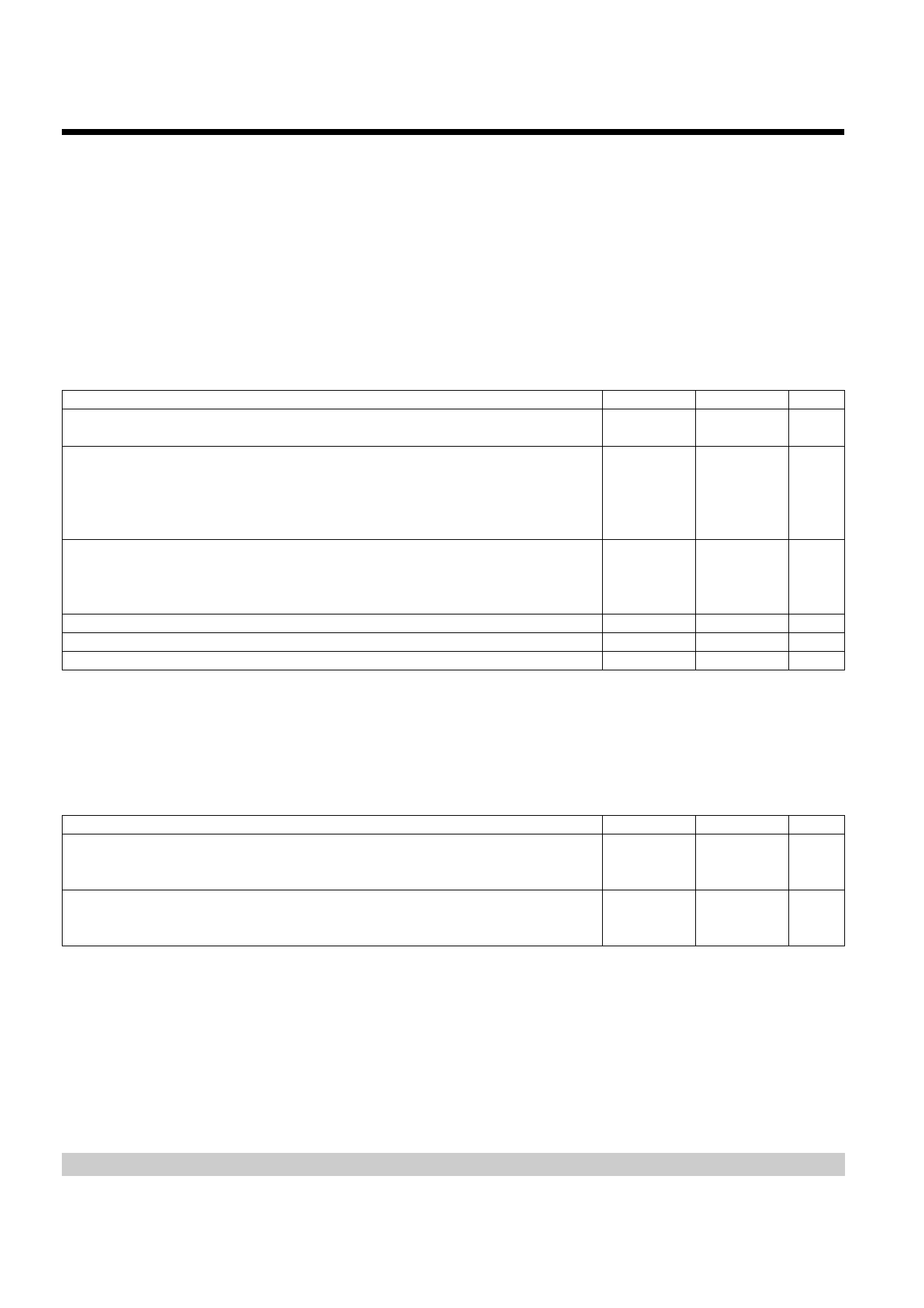
absolute maximum ratings, TA = 25 °C (unless otherwise noted)
RATING
Repetitive peak off-state voltage,
‘4070
‘4350
Non-repetitive peak on-state pulse current (see Notes 1, and 2)
10/160 µs (FCC Part 68, 10/160 µs voltage wave shape, Type A)
5/310 µs (ITU-T K21, 10/700 µs voltage wave shape)
5/320 µs (FCC Part 68, 9/720 µs voltage wave shape, Type B)
10/560 µs (FCC Part 68, 10/560 µs voltage wave shape, Type A)
Non-repetitive peak on-state current (see Notes 1, 2 and 3)
20 ms (50 Hz) full sine wave
16.7 ms (60 Hz) full sine wave
1000 s 50 Hz/60 Hz a.c.
Initial rate of rise of on-state current, Exponential current ramp, Maximum ramp value < 100 A
Junction temperature
Storage temperature range
SYMBOL
VDRM
ITSP
ITSM
diT/dt
TJ
Tstg
VALUE
± 58
±275
UNIT
V
50
40
A
40
30
12
13
2
120
-40 to +150
-65 to +150
A
A/µs
°C
°C
NOTES: 1. Initially the TISP4xxxL3BJ must be in thermal equilibrium with TJ = 25 °C.
2. The surge may be repeated after the TISP4xxxL3BJ returns to its initial conditions.
3. EIA/JESD51-2 environment and EIA/JESD51-3 PCB with standard footprint dimensions connected with 5 A rated printed wiring
track widths. Derate current values at -0.61 %/°C for ambient temperatures above 25 °C
overload ratings, TA = 25 °C (unless otherwise noted)
RATING
Peak overload on-state current, Type A impulse (see Note 4)
10/160 µs
10/560 µs
Peak overload on-state current, a.c. power cross tests UL 1950 (see Note 4)
SYMBOL
IT(OV)M
IT(OV)M
VALUE
UNIT
300
A
150
See Figure 2
for current
A
versus time
NOTE
4: These electrical stress levels may damage the TIS4xxxL3BJ silicon chip. After test, the pass criterion is either that the device is
functional or, if it is faulty, that it has a short circuit fault mode. In the short circuit fault mode, the following equipment is protected
as the device is a permanent short across the line. The equipment would be unprotected if an open circuit fault mode developed.
PRODUCT INFORMATION
2
Share Link: 