VRS1000 데이터 시트보기 (PDF) - Unspecified
부품명
상세내역
제조사
VRS1000 Datasheet PDF : 47 Pages
| |||
VRS1000
VERSA
Datasheet Rev 1.6
Pre-Programmed VRS1000 ISP Program
For your convenience, Goal Semiconductor Inc. has
developed an ISP boot program for the VRS1000 that
allows programming the device’s Flash memory using
the device’s UART0 Serial Port and communicates
with the GoalTender VRS1000 Program that runs
under Windows™ operating system.
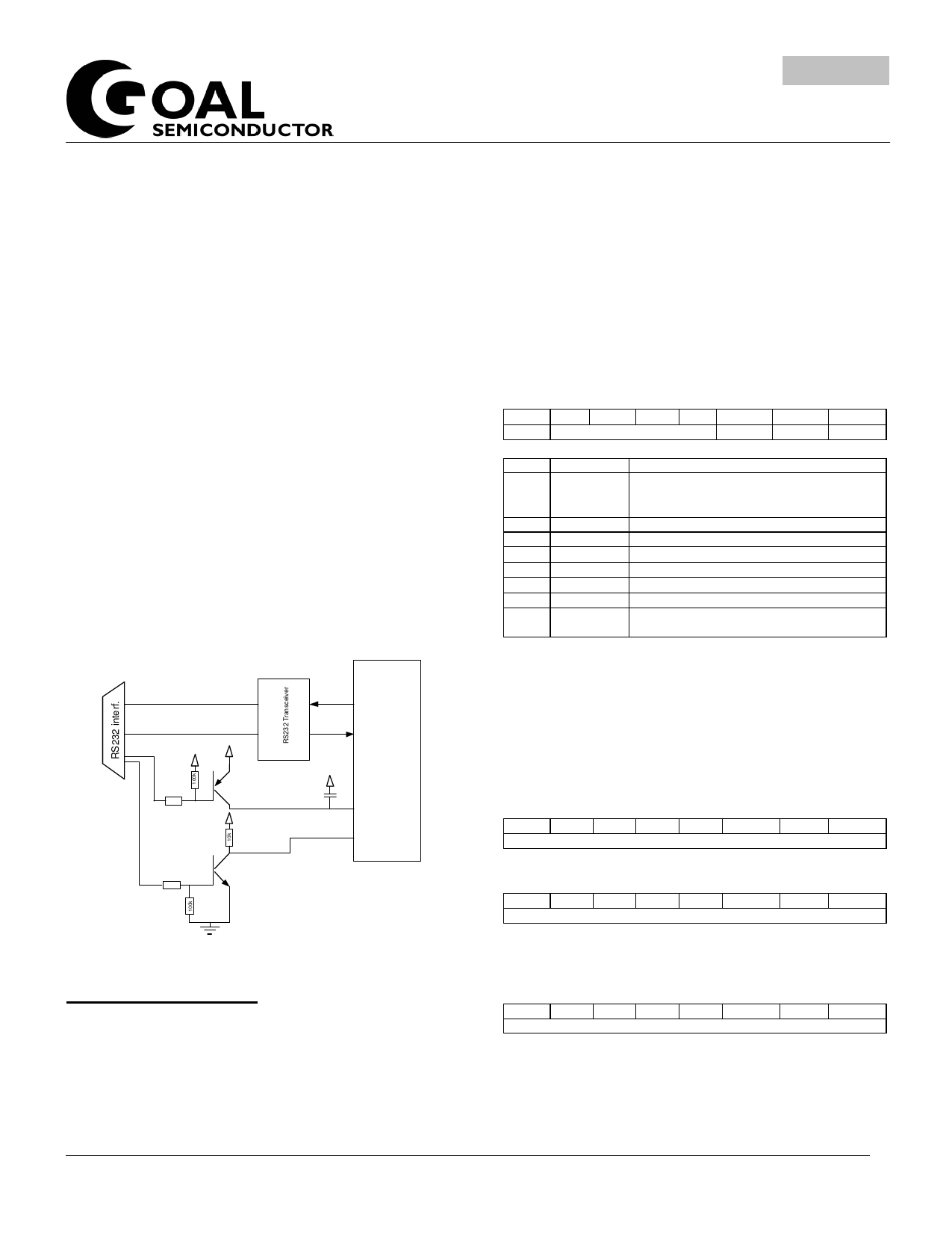
This ISP boot program allows you to program the
VRS1000 on the final application PCB using the
device’s UART interface. The hardware interface to
perform the VRS1000 Flash memory programming
using the ISP boot program is shown below:
If you want to use the Goal Semiconductor parallel
programmer to program the ISP onto the VRS1000,
please specify at the moment you place your order.
For more information regarding features and use of the
ISP Program developed by Goal Semiconductor Inc,
please consult the “VRS1000 ISP Getting Started
Guide”.
FIGURE 5: VRS1000 INTERFACE FOR IN-SYSTEM PROGRAMMING
To PC
V RS100 0
TXD
RXD
PNP
3 30 k
N PN
33 0 k
0.1uF
RES
P4.3
VRS1000 IAP feature
The VRS1000 IAP feature refers to the ability for the
processor to self-program the Flash memory from
within the user program.
Five SFR registers serve to control the IAP operation.
The description of these registers is given below.
The System Control Register
By default upon reset, the IAP feature of the VRS1000
is de-activated. The IAPE bit of the SYSCON register
is used to enable (and disable) the VRS1000 IAP
function as shown below.
TABLE 5: SYSTEM CONTROL REGISTER (SYSCON) – SFR BFH
7
6
WDR
5
4
Unused
3
2
IAPE
1
XRAME
0
ALEI
Bit Mnemonic Description
7
WDR
This is the Watch Dog Timer reset bit. It will
be set to 1 when the reset signal generated
by WDT overflows.
6
Unused
-
5
Unused
-
4
Unused
-
3
Unused
-
2
IAPE
IAP function enable bit
1
XRAME
768 byte on-chip enable bit
0
ALEI
ALE output inhibit bit, which is used to
reduce EMI.
IAP Flash Address and Data Registers
The IAPFADHI and IAPADLO registers are used to
specify the address at which the IAP function will be
performed.
TABLE 6:IAP FLASH ADDRESS HIGH - SFR F4H
7
6
5
4
3
2
1
0
IAPFADHI[15:8]
TABLE 7:IAP FLASH ADDRESS LOW - SFR F5H
7
6
5
4
3
2
1
0
IAPFADLO[15:8]
The IAPFDATA SFR register contains the Data byte
required to perform the IAP function.
TABLE 8:IAP FLASH DATA REGISTER - SFR F6H
7
6
5
4
3
2
1
0
IAPFDATA[7:0]
1134 Ste Catherine Street West, Suite 900, Montreal, Quebec, Canada H3B 1H4 Tel: (514) 871-2447 http://www.goalsemi.com
7
Share Link: 