40TTS12 데이터 시트보기 (PDF) - International Rectifier
부품명
상세내역
제조사
40TTS12 Datasheet PDF : 7 Pages
| |||
40TTS12PbF SAFEIR Series
Bulletin I2233 rev. A 11/05
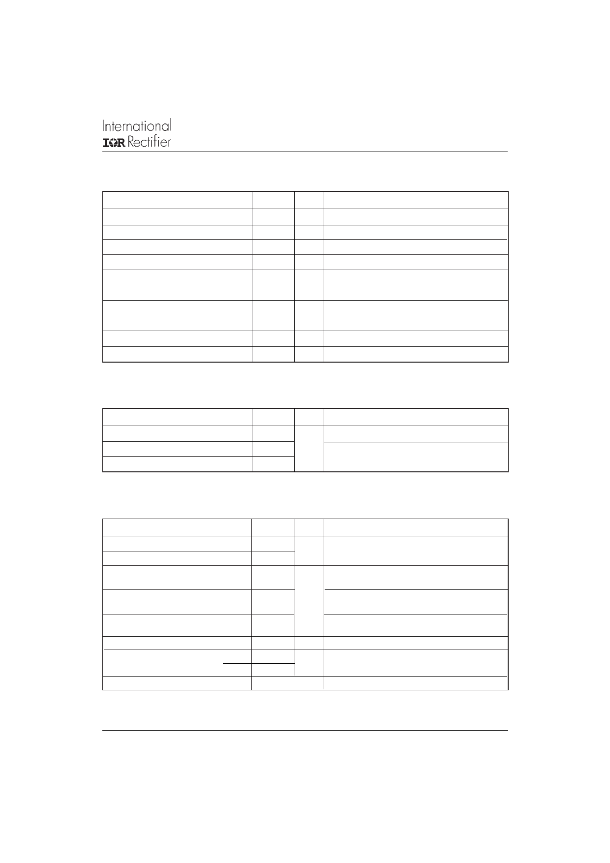
Triggering
Parameters
PGM Max. peak Gate Power
PG(AV) Max. average Gate Power
+ IGM Max. paek positive Gate Current
- VGM Max. paek negative Gate Voltage
IGT Max. required DC Gate Current
to trigger
VGT Max. required DC Gate Voltage
to trigger
VGD Max. DC Gate Voltage not to trigger
IGD Max. DC Gate Current not to trigger
40TTS..
8.0
2.0
1.5
10
35
Units
W
A
V
mA
1.3
V
0.2
1.5
mA
Conditions
Anode supply = 6V, resistive load, TJ = 25°C
Anode supply = 6V, resistive load, TJ = 25°C
TJ = 140°C, VDRM = rated value
TJ = 140°C, VDRM = rated value
Switching
Parameters
tgt Typical turn-on time
trr Typical reverse recovery time
tq Typical turn-off time
40TTS..
0.9
4
110
Units
µs
Conditions
TJ = 25°C
TJ = 140°C
Thermal-Mechanical Specifications
Parameters
40TTS.. Units
Conditions
TJ Max. Junction Temperature Range
Tstg Max. Storage Temperature Range
RthJC Max. Thermal Resistance Junction
to Case
RthJA Max. Thermal Resistance Junction
to Ambient
RthCS Typ. Thermal Resistance Case
to Heatsink
wt Approximate Weight
T Mounting Torque
Min.
Max.
Case Style
- 40 to 140
- 40 to 140
0.8
°C
°C/W
DC operation
60
0.5
Mounting surface, smooth and greased
2 (0.07)
6 (5)
12 (10)
g (oz.)
Kg-cm
(Ibf-in)
TO-220AC
www.irf.com
3
Share Link: 