40TTS12 데이터 시트보기 (PDF) - International Rectifier
부품명
상세내역
제조사
40TTS12 Datasheet PDF : 7 Pages
| |||
40TTS12PbF SAFEIR Series
Bulletin I2233 rev. A 11/05
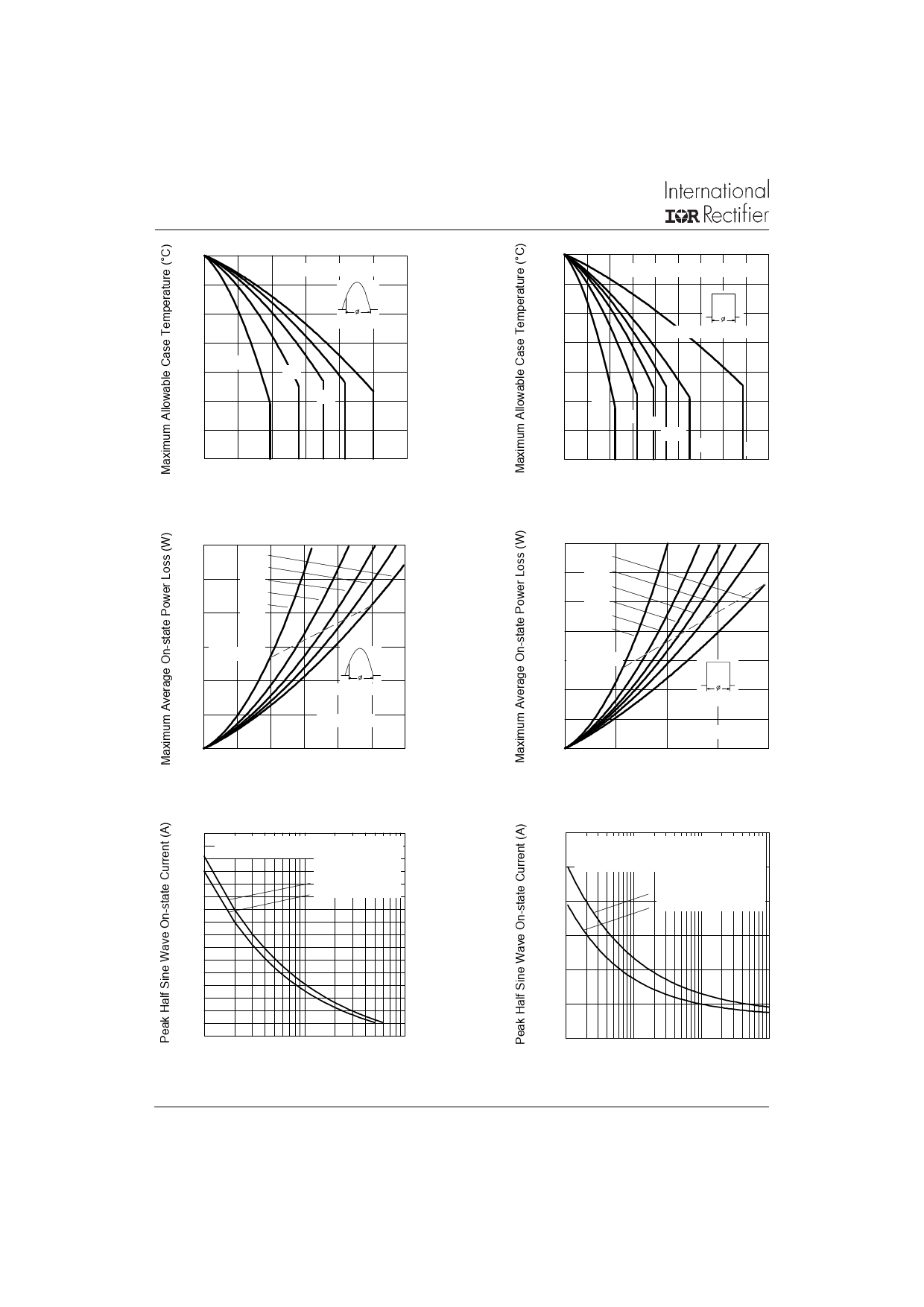
140
RthJC (DC) = 0.8 ˚C/W
130
120
Conduction Angle
110
30˚
100
60˚
90
90˚
120˚
180˚
80
70
0 5 10 15 20 25 30
Average On-state Current (A)
Fig. 1 - Current Rating Characteristics
60
180˚
120˚
50
90˚
60˚
40
30˚
30 RMS Limit
20
Conduction Angle
10
Tj = 125˚C
0
0 5 10 15 20 25 30
Average On-state Current (A)
Fig. 3 - On-state Power Loss Characteristics
280
At Any Rated Load Condition And With
260
Rated Vrrm Applied Following Surge.
Initial Tj = 125˚C
240
@ 60 Hz 0.0083 s
@ 50 Hz 0.0100 s
220
200
180
160
140
120
1
10
100
Number of Equal Amplitude Half Cycle Current Pulses (N)
Fig. 5 - Maximum Non-Repetitive Surge Current
4
140
RthJC (DC) = 0.8 ˚C/W
130
120
Conduction Period
110
100
90
30˚
80
60˚ 90˚
120˚
180˚
DC
70
0 5 10 15 20 25 30 35 40 45
Average On-state Current (A)
Fig. 2 - Current Rating Characteristics
70
DC
60 180˚
120˚
50
90˚
60˚
40
30˚
30 RMS Limit
20
Conduction Period
10
Tj = 125˚C
0
0
10
20
30
40
Average On-state Current (A)
Fig. 4 - On-state Power Loss Characteristics
400
Maximum Non Repetitive Surge Current
Versus Pulse Train Duration. Control
350 Of Conduction May Not Be Maintained.
Initial Tj = 125˚C
No Voltage Reapplied
300
Rated Vrrm Reapplied
250
200
150
100
0.01
0.1
1
10
Pulse Train Duration (s)
Fig. 6 - Maximum Non-Repetitive Surge Current
www.irf.com
Share Link: 