MAX17040 데이터 시트보기 (PDF) - Maxim Integrated
부품명
상세내역
제조사
MAX17040 Datasheet PDF : 13 Pages
| |||
MAX17040/MAX17041
1-Cell/2-Cell Fuel Gauge with ModelGauge
Pin Description
PIN
UCSP TDFN
NAME
A1
8
SDA
A2
7
SCL
A3
1
CTG
B1
6
EO
B2
—
N.C.
B3
2
CELL
C1
5
SEO
C2
3
VDD
C3
4
GND
—
—
EP
FUNCTION
Serial Data Input/Output. Open-drain 2-wire data line. Connect this pin to the DATA signal of the
2-wire interface. This pin has a 0.2µA typical pulldown to sense disconnection.
Serial Clock Input. Input only 2-wire clock line. Connect this pin to the CLOCK signal of the
2-wire interface. This pin has a 0.2µA typical pulldown to sense disconnection.
Connect to Ground. Connect to GND during normal operation.
External 32kHz Clocking Signal. Input for external clocking signal to be the primary system clock.
Configured to implement interrupt feature with a pulldown set on SEO pin.
No Connect. Do not connect.
Battery-Voltage Input. The voltage of the cell pack is measured through this pin.
External 32kHz Clocking Signal Enable Input. Input to enable external clocking signal on EO
pin with a pullup state; a pulldown state to configure the interrupt feature. External 32kHz clock
enable. Connects logic-low to enable external interrupt.
Power-Supply Input. 2.5V to 4.5V input range. Connect to system power through a decoupling
network. Connect a 10nF typical decoupling capacitor close to pin.
Ground. Connect to the negative power rail of the system.
Exposed Pad (TDFN Only). Connect to ground.
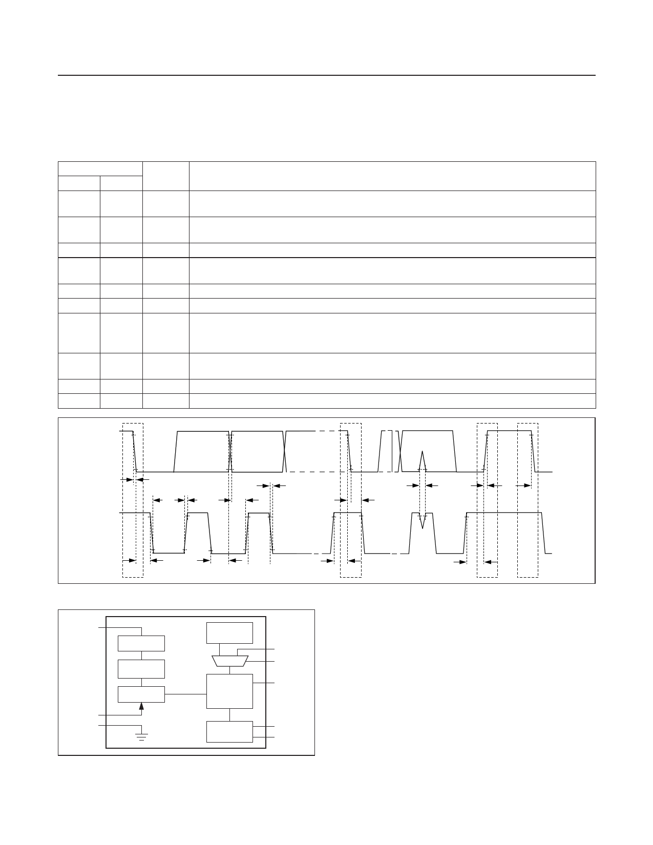
SDA
tF
tF
tSU:DAT
tLOW
tR
tHD:STA
tSP
tR
tBUF
SCL
tHD:STA
S
tHD:DAT
Figure 1. 2-Wire Bus Timing Diagram
VDD
CELL
GND
BIAS
VOLTAGE
REFERENCE
ADC (VCELL)
TIME BASE
(32kHz)
MAX17040
MAX17041
STATE
MACHINE
(SOC, RATE)
IC
GROUND
2-WIRE
INTERFACE
Figure 2. Block Diagram
tSU:STA
Sr
tSU:STO
P
S
Detailed Description
Figure 1 shows the 2-wire bus timing diagram, and Figure
2 is the MAX17040/MAX17041 block diagram.
EO
SEO
ModelGauge Theory of Operation
CTG
The MAX17040/MAX17041 use a sophisticated bat-
tery model, which determines the SOC of a nonlinear
Li+ battery. The model effectively simulates the internal
dynamics of a Li+ battery and determines the SOC. The
SDA
model considers the time effects of a battery caused
SCL
by the chemical reactions and impedance in the bat-
tery. The MAX17040/MAX17041 SOC calculation does
not accumulate error with time. This is advantageous
www.maximintegrated.com
Maxim Integrated │ 5
Share Link: 