MC33797R2 데이터 시트보기 (PDF) - Freescale Semiconductor
부품명
상세내역
제조사
MC33797R2 Datasheet PDF : 32 Pages
| |||
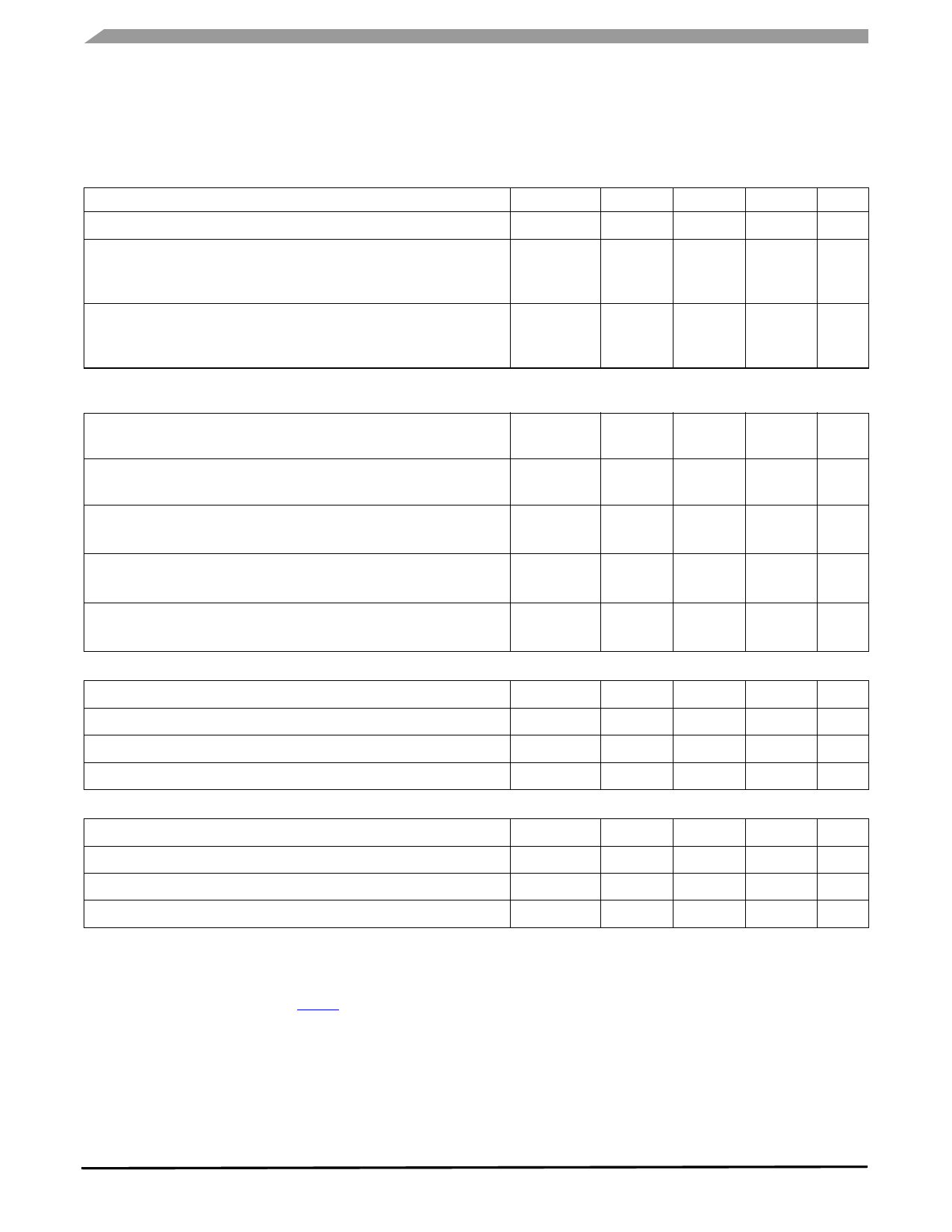
STATIC ELECTRICAL CHARACTERISTICS
Table 3. Static Electrical Characteristics (continued)
Characteristics noted under conditions 4.75 V ≤ VDD ≤ 5.25 V; 7.0 V ≤ VVFIRE_XX ≤ 35 V; VVDIAG_X = VVFIRE_XX; FEN 1 = FEN 2
= VDD; RR_LIMIT_X = 10 kΩ ±1%, RR_DIAG = 10 kΩ ±1%, -40°C ≤ TA ≤ +85°C, GND = 0 unless otherwise noted. Typical values
noted reflect the approximate parameter means at TA = 25°C under nominal conditions unless otherwise noted.
Characteristic
Symbol
Min
Typ
Max
Unit
R_HS Short Threshold
RHSS
2.8
–
4.1
kΩ
VFIRE_XA & VFIRE_XB Current during High Side Safing Test at Open
Threshold
VFIRE_1A & VFIRE_1B or VFIRE_2A & VFIRE_2B
I1HSO
µA
270
360
410
VFIRE_XA & VFIRE_XB Current during High Side Safing Test at Short
Threshold
VFIRE_1A & VFIRE_1B or VFIRE_2A & VFIRE_2B
I1HSS
µA
287
385
436
HIGH-SIDE SAFING SENSOR DIAGNOSTICS WITH 1 SAFING SENSOR IN FIRING PATH CONNECTED TO VFIRE_1A AND VFIRE_2A
TERMINALS (GUARANTEED BY DESIGN) ($C0 COMMAND)
Total VFIRE_XX Current during High Side Safing Test at Open Threshold
VFIRE_1A, VFIRE_1B, VFIRE_2A & VFIRE_2B terminals
Total VFIRE_XX Current during High Side Safing Test at Short Threshold
VFIRE_1A, VFIRE_1B, VFIRE_2A & VFIRE_2B terminals
R_HS Valid Resistor Range
15 V ≤ VVDIAG_X ≤ 35 V
R_HS Open Threshold
15 V ≤ VVDIAG_X ≤ 35 V
R_HS Short Threshold
15 V ≤ VVDIAG_X ≤ 35 V
I2HSO
I2HSS
R2HS
R2HSO
R2HSS
574
605
1.99
2.93
1.41
705
748
–
3.35
1.61
µA
835
µA
892
kΩ
2.93
kΩ
4.43
kΩ
1.99
R_LIMIT RESISTOR DIAGNOSTICS ($C8 COMMAND)
R_LIMIT Valid Resistor Range
R_LIMIT Open Threshold (“Out of Range Threshold”)
R_LIMIT Short-to-Ground Threshold (“Out of Range Threshold”)
Maximum External Capacitance to Ground
R_DIAG RESISTOR DIAGNOSTICS ($C8 COMMAND) (18)
RRL
RRLO
RRLS
CRL
4.32
60
3.0
–
–
45.3
kΩ
76
105
kΩ
3.5
4.31
kΩ
–
20
pF
R_DIAG Valid Resistor Range
R_DIAG Open Threshold (“Out of Range Threshold”)
R_DIAG Short-to-Ground Threshold (“Out of Range Threshold”)
Maximum External Capacitance to Ground
RRD
8.0
–
13
kΩ
RRDO
13
23
60
kΩ
RRDS
3.0
5.4
8.0
kΩ
CRD
–
–
20
pF
Notes
18. By changing the R_DIAG resistor value, the resistance thresholds can be varied by a linear relationship.The R_DIAG resistance could
be changed by ±10% to shift the thresholds by ±10%. Design goal for resistance threshold change is ±15%. R_DIAG threshold limit may
have to be changed to accommodate ±15% change. Example: Shifting the R_DIAG resistance value ±10%, the resistance threshold
will change by ±10%. Refer to Table 4.
33797
10
Analog Integrated Circuit Device Data
Freescale Semiconductor
Share Link: 