PS2513-1 데이터 시트보기 (PDF) - NEC => Renesas Technology
부품명
상세내역
제조사
PS2513-1 Datasheet PDF : 13 Pages
| |||
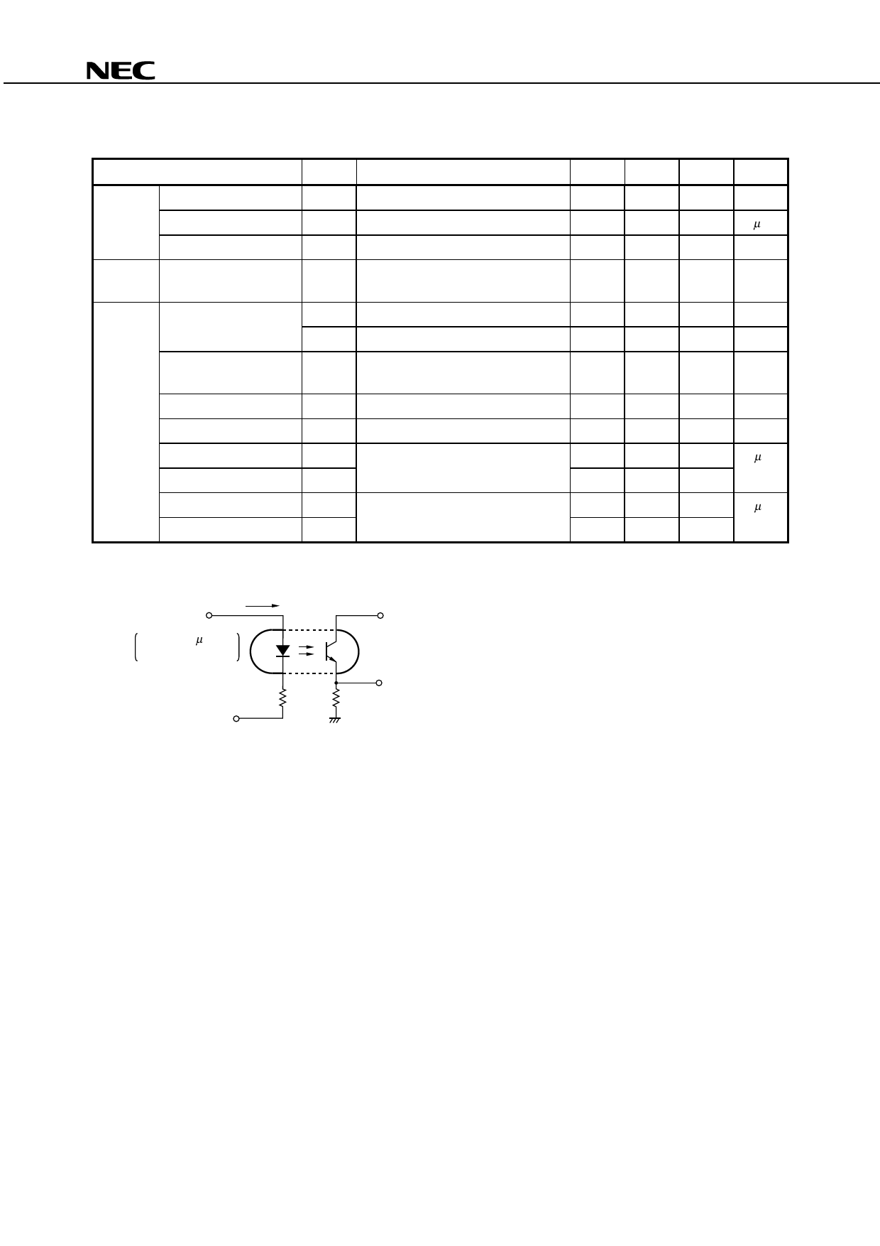
PS2513-1,PS2513L-1
ELECTRICAL CHARACTERISTICS (TA = 25°C)
Parameter
Symbol
Conditions
Diode
Forward Voltage
VF
IF = 5 mA
Reverse Current
IR
VR = 5 V
Terminal Capacitance
Ct V = 0 V, f = 1.0 MHz
Transistor Collector to Emitter Dark
Current
ICEO VCE = 120 V, IF = 0 mA
Coupled Current Transfer Ratio CTR1 IF = 1 mA, VCE = 5 V
(IC/IF)
CTR2 IF = 5 mA, VCE = 5 V
Collector Saturation
Voltage
VCE(sat) IF = 10 mA, IC = 2 mA
Isolation Resistance
RI-O
VI-O = 1.0 kVDC
Isolation Capacitance
Rise Time*1
Fall Time*1
Turn-on Time*1
Turn-off Time*1
CI-O V = 0 V, f = 1.0 MHz
tr
VCC = 5 V, IC = 2 mA, RL = 100 Ω
tf
ton
VCC = 5 V, IF = 5 mA, RL = 1.9 kΩ
toff
*1 Test circuit for switching time
IF
Pulse Input
PW = 100 µs
Duty Cycle = 1/10
50 Ω
VCC
VOUT
RL = 100 Ω, 1.9 kΩ
MIN. TYP. MAX. Unit
1.1
1.3
V
5
µA
30
pF
100
nA
25
75
100
%
50
125
200
%
0.3
V
1011
Ω
0.5
pF
3
µs
4
5
60
µs
25
60
CAUTIONS REGARDING NOISE
Be aware that when voltage is applied suddenly between the photocoupler’s input and output or between
corrector-emitters at startup, the output side may enter the on state, even if the voltage is within the absolute
maximum ratings.
Data Sheet PN10163EJ02V0DS
5
Share Link: 