SC220EVB 데이터 시트보기 (PDF) - Semtech Corporation
부품명
상세내역
제조사
SC220EVB Datasheet PDF : 14 Pages
| |||
SC220 x
SC220Q
Applications Information (Cont.)
The high-side switch is then held off for a period sufficient
to allow inductor current to decay. When the output
voltage is close to the nominal regulation point, this will
look similar to constant current limiting. As the output
voltage falls, imposed off-time is such that the frequency
will drop so that the inductor will have appropriate time
to reset. This may cause the average current to reduce,
giving a mild ‘fold-back’ characteristic to the current limit,
where the average load current drops as the output
voltage collapses (although the peak current maintains its
nominal value). In a short-circuit condition, the system
runs continuously at this reduced frequency.
X-EMITM technology works by placing two small air-core
inductors adjacent to one another in anti-phase position,
where the magnetic fields of each inductor partially cancel
one another to reduce EMI. The net flux from the two
inductors, partially cancels the wide leakage paths caused
by the wide geometry, while still storing the energy of the
inductors in series. This approach uses multiple air core
inductors implemented using printed circuit traces.
Because these traces may be located on internal layers of
the PCB, inductors can be designed with almost no impact
on the available PCB area for components on the surface
of the board. (See the efficiency curves using X-EMI™
inductor technology on page 6).
External Components
Load Transient Response
The SC220/Q features excellent regulation during line and
load transients. This is due to the nature of the proprietary
control method and the high di/dt allowed by the use of a
small inductor. This allows for best performance while
providing the benefit of using a small low cost output
capacitor. VOUT shows only tens of milivolts of ripple voltage
during a load current step change of 1mA to 650mA within
hundreds of nanoseconds, using a 1μF output capacitor.
(See the typical performance curves on page 7).
The input and output capacitors used for the operation of
the SC220/Q should be multilayer ceramic capacitors,
preferably with X7R or X5R dielectric. SC220/Q is opti-
mized to operate with the input and output capacitance
of 1μF typical. In practice, the self-resonant frequency of
surface mount capacitors of this type is well below 20MHz
ripple frequency, so efforts to minimize output ripple may
best be focused on minimizing the inductance of the
output capacitor and the length of the circuit path to
ground rather than on increasing the capacitance value of
the output capacitor.
X-EMI™ Inductor Technology
The SC220/Q is the industry’s first buck regulator that
enables designers to draw their own inductors directly on
the PC board. This patented technology is called as X-
EMI™ inductor technology and is different from
conventional PCB trace inductors. Conventional PCB trace
inductors can be used with high-frequency switchers, but
they exhibit significant EMI issues. X-EMI™ inductor tech-
nology solves these EMI problems and can meet or exceed
the EMI performance of conventional chip inductors.
The inductor should be a high current inductor rated for
currents at least up to 1A. Typical power inductors may be
too lossy at 20MHz unless specifically designed for high
frequency operation. For inductor value of 220nH, it may
be preferred to use wire-wound RF chokes, many of which
are rated for appropriate currents.
Some Recommended External Components
Value Manufacturer
Part Number
Package
L
CIN
COUT
0.22μH
0.24μH
1μF
1μF
Coilcraft
Coilcraft
Murata
Murata
XFL2005-221ME
0603LS-241XJL
GRM155R61C105KA12
GRM155R61C105KA12
2x2mm
0603
0402
0402
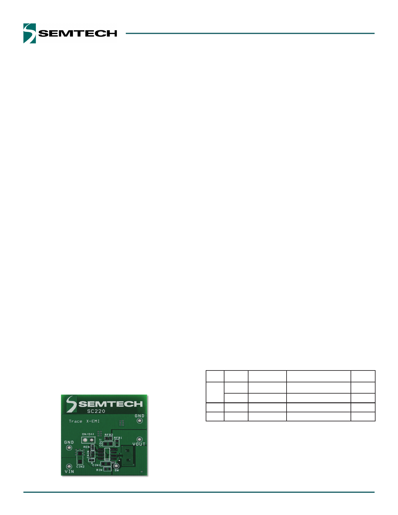
Figure 1. Top view of an evaluation board with X-EMI inductor
10
Share Link: 