SHT11 데이터 시트보기 (PDF) - Unspecified
부품명
상세내역
제조사
SHT11 Datasheet PDF : 9 Pages
| |||
SHT1x / SHT7x Relative Humidity & Temperature Sensor System
4 Applications Information
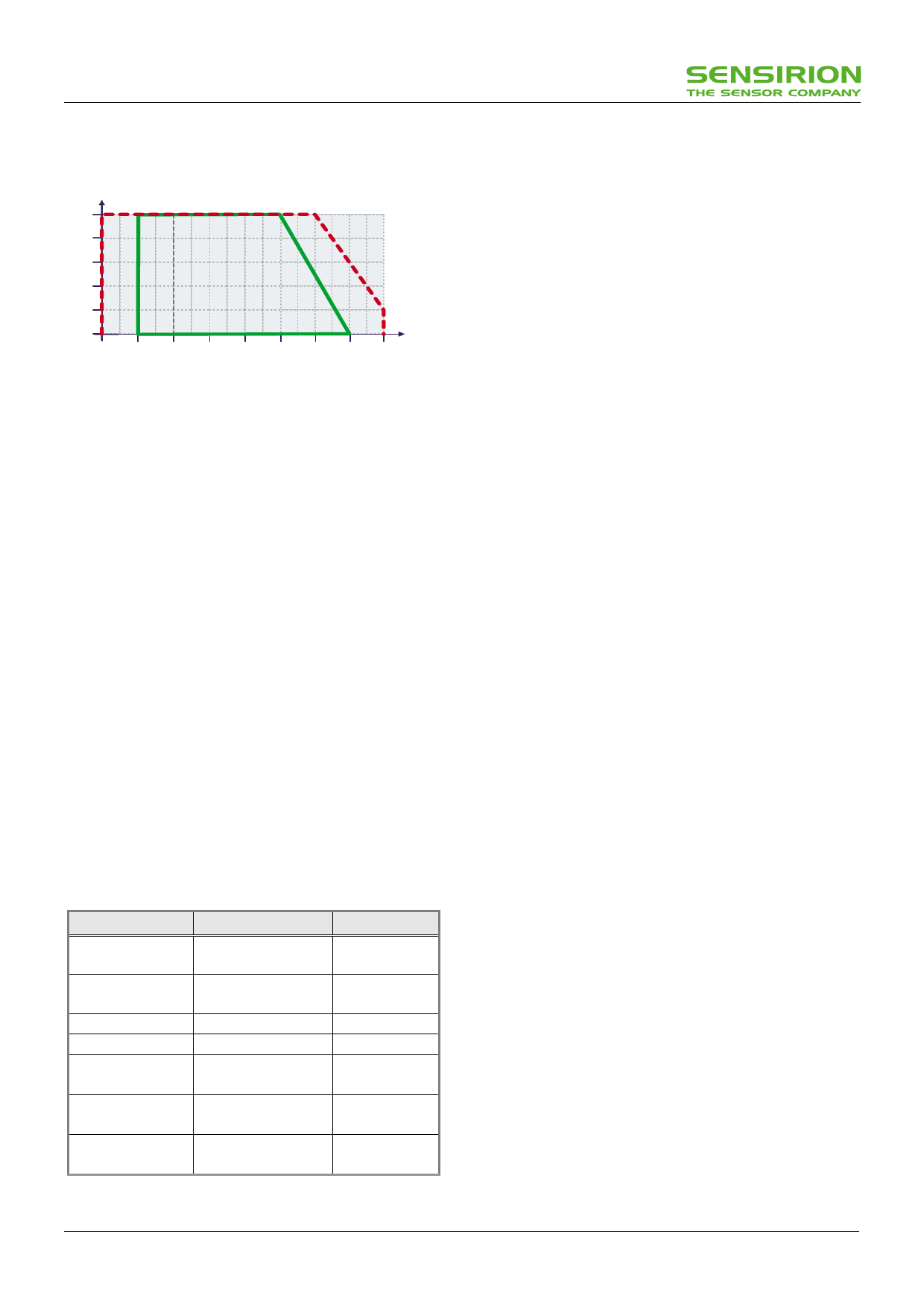
4.1 Operating and Storage Conditions
[%RH]
100
80
Maximum operating
conditions
60
Normal operating
40
conditions
20
0
[°C]
-40 -20 0 20 40 60 80 100 120
Figure 11 Recommended operating conditions
Conditions outside the recommended range may temporarily
offset the RH signal up to ±3 %RH. After return to normal
conditions it will slowly return towards calibration state by
itself. See 4.3 “Reconditioning Procedure” to accelerate this
process. Prolonged exposure to extreme conditions may
accelerate ageing.
4.2 Exposure to Chemicals
Vapors may interfere with the polymer layers used for
capacitive humidity sensors. The diffusion of chemicals into
the polymer may cause a shift in both offset and sensitivity.
In a clean environment the contaminants will slowly outgas.
The reconditioning procedure described below will
accelerate this process.
High levels of pollutants may cause permanent damage to
the sensing polymer.
4.3 Reconditioning Procedure
The following reconditioning procedure will bring the sensor
back to calibration state after exposure to extreme conditions
or chemical vapors.
80-90 °C (176-194°F) at < 5 %RH for 24h (baking) followed by
20-30 °C (70-90°F) at > 74 %RH for 48h (re-hydration)
4.4 Qualifications
Extensive tests were performed in various environments.
Please contact SENSIRION for additional information.
Environment
Norm
Results(1)
Temperature
Cycles
JESD22-A104-B -40 °C Within
/ 125°C, 1000cy
Specifications
HAST
JESD22-A110-B
Reversible shift
Pressure Cooker 2.3bar 125°C 85%RH by +2 %RH
Salt Atmosphere DIN-50021ss
Within Spec.
Condensing Air -
Within Spec.
Freezing cycles -20 / +90°C, 100cy
fully submerged 30min dwell time
Reversible shift
by +2 %RH
Various Automotive DIN 72300-5
Chemicals
Within
Specifications
Cigarette smoke Equivalent to 15years Within
in a mid-size car
Specifications
Table 9 Qualification tests (excerpt)
4.5 ESD (Electrostatic Discharge)
ESD immunity is qualified according to MIL STD 883E,
method 3015 (Human Body Model at ±2 kV)).
Latch-up immunity is provided at a force current of ±100 mA
with Tamb = 80 °C according to JEDEC 17.
See application note “ESD, Latchup and EMC” for more
information.
4.6 Temperature Effects
The relative humidity of a gas strongly depends on its
temperature. It is therefore essential to keep humidity
sensors at the same temperature as the air of which the
relative humidity is to be measured.
If the SHTxx shares a PCB with electronic components that
give off heat it should be mounted far away and below the
heat source and the housing must remain well ventilated.
To reduce heat conduction copper layers between the
SHT1x and the rest of the PCB should be minimized and a
slit may be milled in between. ( See figure 14 )
4.7 Materials Used for Sealing / Mounting
Many materials absorb humidity and will act as a buffer,
increasing response times and hysteresis. Materials in the
vicinity of the sensor must therefore be carefully chosen.
Recommended materials are:
All Metals, LCP, POM (Delrin), PTFE (Teflon), PE, PEEK,
PP, PB, PPS, PSU, PVDF, PVF
For sealing and gluing (use sparingly):
High filled epoxy for electronic packaging (e.g. glob top,
underfill), and Silicone are recommended.
4.8 Membranes
A membrane can be used to prevent dirt from entering the
housing and to protect the sensor. It will also reduce peak
concentrations of chemical vapors. For optimal response
times air volume behind the membrane must be kept to a
minimum.
4.9 Light
The SHTxx is not light sensitive. Prolonged direct exposure
to sunshine or strong UV radiation may age the housing.
4.10 Wiring Considerations and Signal Integrity
Carrying the SCK and DATA signal parallel and in close
proximity (e.g. in wires) for more than 10cm may result in
cross talk and loss of communication. This may be resolved
by routing VDD and/or GND between the two data signals.
Please see the application note “ESD, Latchup and EMC” for
more information.
Power supply pins (VDD, GND) should be decoupled with a
100 nF capacitor if wires are used.
(1) The temperature sensor passed all tests without any detectable drift. Package and electronics also passed 100%
www.sensirion.com
v2.01 March 2003
6/9
Share Link: 