CA4800C 데이터 시트보기 (PDF) - Freescale Semiconductor
부품명
상세내역
제조사
CA4800C Datasheet PDF : 4 Pages
| |||
MOTOROLA
Freescale Semiconductor, Inc.
SEMICONDUCTOR TECHNICAL DATA
Order this document
by CA4800C/D
The RF Line
Wideband Linear Amplifiers
. . . designed for amplifier applications in 50 ohm systems requiring wide
bandwidth, low noise and low–distortion. This hybrid provides excellent gain
stability with temperature and linear amplification as a result of the push–pull
circuit design.
• Specified Characteristics at VCC = 24 V for CA4800C; 12 V for CA4812C;
15 V for CA4815C, TC = 25°C:
Frequency Range — 10 to 1000 MHz
Output Power — 400 mW Typ @ 1 dB Compression, f = 900 MHz
Power Gain — 17.5 dB Typ @ 1000 MHz
Noise Figure — 6.5 dB Typ @ f = 500 MHz
ITO — 38 dBm Typ @ 1000 MHz
• All Gold Metallization for Improved Reliability
• CA4812C is Optimized for 12 V Operation
• CA4815C is Optimized for 15 V Operation
CA4800C,CS
CA4812C,CS
CA4815C,CS
17 dB
10–1000 MHz
400 mW
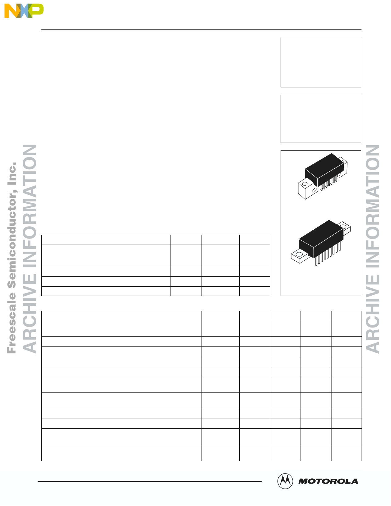
WIDEBAND
LINEAR AMPLIFIERS
CASE 714P–03, STYLES 2, 3
CA4800C, CA4812C, CA4815C
MAXIMUM RATINGS (TA = 25°C unless otherwise noted)
Rating
Symbol
Supply Voltage
CA4800C,CS
VCC
CA4815C,CS
CA4812C,CS
RF Input Power
Pin
Storage Temperature
Tstg
Operating Case Temperature Range
TC
Value
28
18
14
+14
–40 to +100
–20 to +100
Unit
V
dBm
°C
°C
CASE 714T–03, STYLES 1, 2
CA4800CS, CA4812CS,
CA4815CS
ELECTRICAL CHARACTERISTICS (TC = 25°C, VCC = 24 V for CA4800C; 12 V for CA4812C; 15 V for CA4815C, 50 Ohm System)
Characteristic
Symbol
Min
Typ
Max
Unit
Supply Current
CA4800C,CS
IDC
CA4812C,CS; CA4815C,CS
—
220
240
mA
—
380
400
Power Gain (f = 1000 MHz)
PG
16.5
17.5
18.5
dB
Bandwidth (3 dB Down at 10 MHz)
BW
10
—
1000
MHz
Gain Flatness (f = 40–1000 MHz)
FL
—
1
2
dB
Power Output — 1 dB Compression (f = 900 MHz)
Input/Output VSWR f = 40–900 MHz
Input/Output VSWR f = 900–1000 MHz
Po 1dB
300
400
—
mW
VSWR
—
—
—
2:1
—
—
2.6:1
Noise Figure, Broadband f = 500 MHz
Noise Figure, Broadband f = 1000 MHz
NF
—
6.5
8
dB
—
7.5
9
Third Order Intercept (f1 = 10–1000 MHz, See Figure 1)
Second Harmonic Distortion (Po = 100 mW, f2H = 1000 MHz)
Second Order Intermodulation Distortion
(Po = 2.75 dBm, f1 = 373 MHz, f2 = 450 MHz, See Figure 1)
Intermodulation Distortion, 3 Tone
(f = 860 MHz, Psync = 200 mW, See Figure 2)
ITO
37
38
—
dBm
dso
—
–50
–40
dB
IM2
—
—
–60
dB
IM3
—
–60
—
dB
REV 1
MOTOROLA RF DEVICE DATA
CA4800C,CS CA4812C,CS CA4815C,CS
Motorola, Inc. 1995
For More Information On This Product,
Go to: www.freescale.com
1
Share Link: 