MAX6721 데이터 시트보기 (PDF) - Maxim Integrated
부품명
상세내역
제조사
MAX6721 Datasheet PDF : 19 Pages
| |||
Dual/Triple Ultra-Low-Voltage SOT23 µP
Supervisory Circuits
restarts. The MAX6715/MAX6717/MAX6719/MAX6721/
MAX6723/MAX6725/MAX6727/MAX6728 contain open-
drain reset outputs, while the MAX6716/MAX6718/
MAX6720/MAX6722/MAX6724/MAX6726/MAX6729
contain push-pull reset outputs. The MAX6727 provides
two separate open-drain RST outputs driven by the
same internal logic.
Manual Reset Input
Many microprocessor-based products require manual
reset capability, allowing the operator, a test techni-
cian, or external logic circuitry to initiate a reset. A logic
low on MR asserts the reset output. Reset remains
asserted while MR is low and for the reset timeout peri-
od (tRP) after MR returns high. This input has an internal
50kΩ pullup resistor to VCC1 and can be left uncon-
nected if not used. MR can be driven with TTL or
CMOS logic levels, or with open-drain/collector outputs.
Connect a normally open momentary switch from MR to
GND to create a manual reset function; external
debounce circuitry is not required. If MR is driven from
long cables or if the device is used in a noisy environ-
ment, connect a 0.1µF capacitor from MR to GND to
provide additional noise immunity.
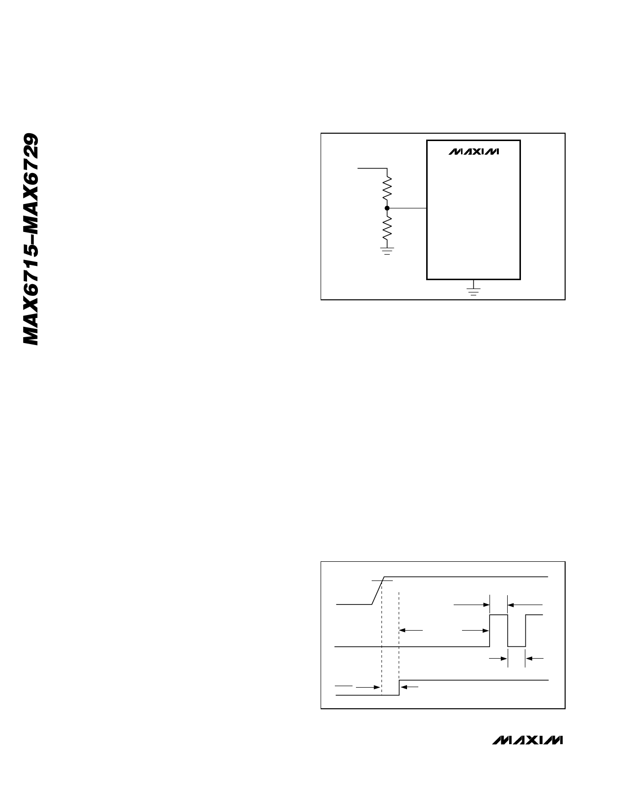
Adjustable Input Voltage
The MAX6719/MAX6720 and MAX6723–MAX6727 provide
an additional input to monitor a third system voltage. The
threshold voltage at RSTIN is typically 626mV. Connect a
resistor-divider network to the circuit as shown in Figure 1
to establish an externally controlled threshold voltage,
VEXT_TH.
VEXT_TH = 626mV((R1 + R2)/R2)
Low leakage current at RSTIN allows the use of large-
valued resistors resulting in reduced power consump-
tion of the system.
Watchdog Input
The watchdog monitors µP activity through the watch-
dog input (WDI). To use the watchdog function, con-
nect WDI to a bus line or µP I/O line. When WDI
remains high or low for longer than the watchdog time-
out period, the reset output asserts.
The MAX6721–MAX6729 include a dual-mode watch-
dog timer to monitor µP activity. The flexible timeout
architecture provides a long period initial watchdog
mode, allowing complicated systems to complete
lengthy boots, and a short period normal watchdog
mode, allowing the supervisor to provide quick alerts
VEXT_TH
MAX6719/
MAX6720/
R1
MAX6723–
MAX6727
RSTIN
R2
GND
Figure 1. Monitoring a Third Voltage
when processor activity fails. After each reset event
(VCC power-up/brownout, manual reset, or watchdog
reset), there is a long initial watchdog period of 35s
minimum. The long watchdog period mode provides an
extended time for the system to power-up and fully ini-
tialize all µP and system components before assuming
responsibility for routine watchdog updates.
The normal watchdog timeout period (1.12s min)
begins after the first transition on WDI before the con-
clusion of the long initial watchdog period (Figure 2).
During the normal operating mode, the supervisor will
issue a reset pulse for the reset timeout period if the µP
does not update the WDI with a valid transition (high-to-
low or low-to-high) within the standard timeout period
(1.12s min).
Power-Fail Comparator
PFI is the noninverting input to a comparator. If PFI is
less than VPFI (626.5mV), PFO goes low. Common uses
for the power-fail comparator include monitoring prereg-
ulated input of the power supply (such as a battery) or
VTH
VCC
tWDI-NORMAL
1.12s MAX
tWDI-STARTUP
35s MAX
WDI
1.12s MAX
RESET
tRP
Figure 2. Normal Watchdog Startup Sequence
10 ______________________________________________________________________________________
Share Link: 