HIP0045 데이터 시트보기 (PDF) - Intersil
부품명
상세내역
제조사
HIP0045 Datasheet PDF : 10 Pages
| |||
HIP0045
Absolute Maximum Ratings
Maximum Output Voltage, VOUT . . . . . . . . . . . . . . . . . . .-0.7 to VOC
Peak Output Load Current, ILOAD . . . . . As Specified for ISC, ILIM
Continuous Output Load Current, IOUT (All 8 Outputs ON) . . . . 0.5A
Continuous Output Load Current, IOUT (Any one Output ON) . . 1A
Total Average Current, IOUT (All 8 Outputs) . . . . . . . . . . . . . . . 4.5A
Reverse Peak Current Drive, Any one Output, IRD; t ≤ 2ms . . . -3A
DC Logic Supply, VCC . . . . . . . . . . . . . . . . . . . . . . . . . . . . -0.3 to 7V
Input Voltage, All Inputs and Data Lines . . . . . . . -0.3 to VCC +0.3V
Operating Conditions
Temperature Range . . . . . . . . . . . . . . . . . . . . . . . . . -40oC to 125oC
Logic Supply Voltage, VCC . . . . . . . . . . . . . . . . . . . . . 4.5V to 5.5V
Thermal Information
Thermal Resistance (Typical, Note 6)
θJA (oC/W) θJC (oC/W)
PSOP Package . . . . . . . . . . . . . . . . . .
40
2
Maximum Junction Temperature, TJ . . . . . . . . . . . . . . . . . . . .150oC
Maximum
Maximum
Storage Temperature Range,
Lead Temperature (Soldering
TSTG
10s) .
.
.
.
.
.
.
.
.
-55oC to 150oC
. . . . . . . .265oC
Die Characteristics
Back Side Potential . . . . . . . . . . . . . . . . . . .V- (GND Pin, Heat Sink)
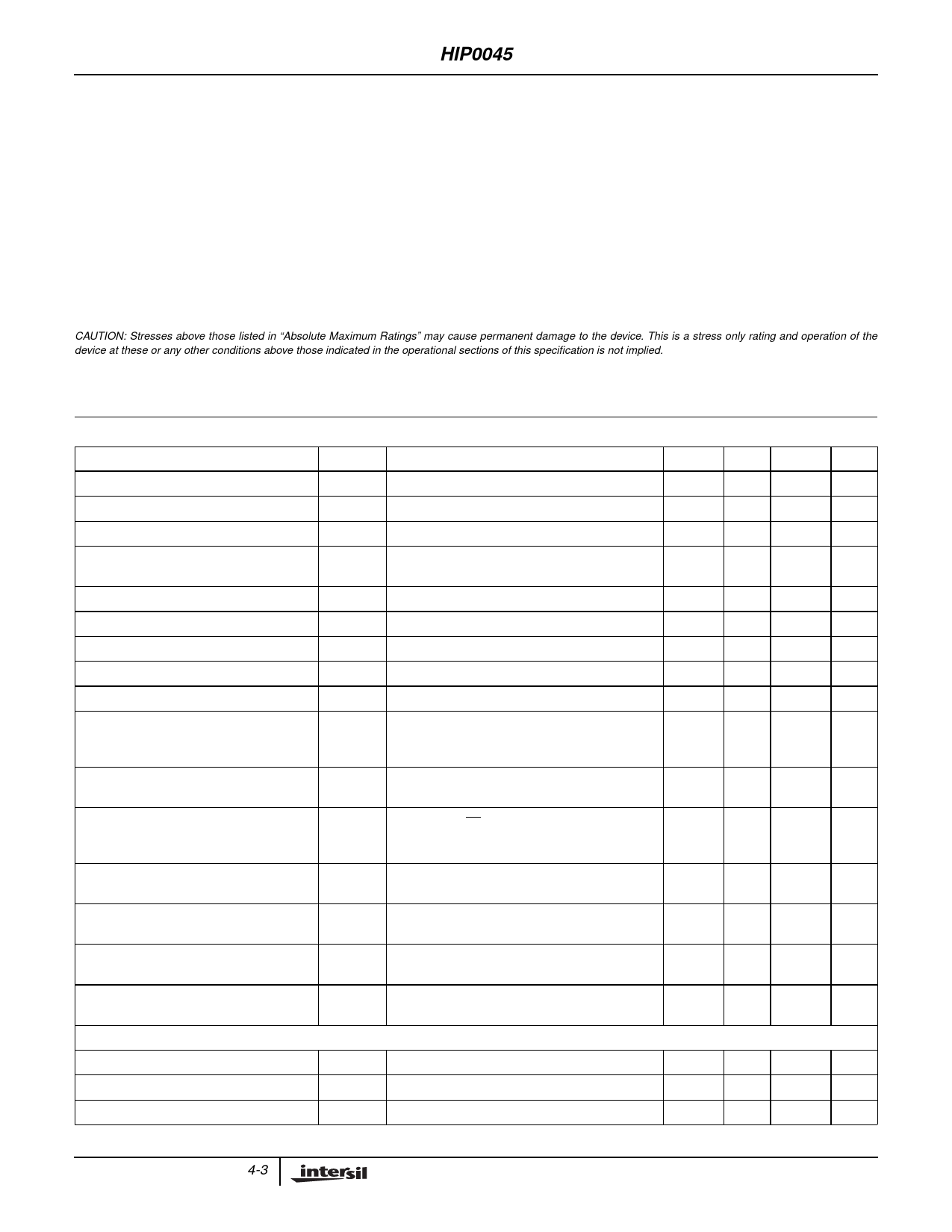
CAUTION: Stresses above those listed in “Absolute Maximum Ratings” may cause permanent damage to the device. This is a stress only rating and operation of the
device at these or any other conditions above those indicated in the operational sections of this specification is not implied.
NOTE:
6. θJA Rated with standard PC Board, θJC rated with infinite heat sink.
Electrical Specifications VCC = 4.5V to 5.5V, TA = -40oC to 125oC, Unless Otherwise Specified
PARAMETER
SYMBOL
TEST CONDITIONS
MIN TYP MAX UNITS
Standby Current, No Load
Supply Current, Full Load
Output Clamping Voltage (Note 7)
Output Clamping Energy
ICCO
ICC
VOC
EOC
No Load
All Outputs ON, 0.5A Load Per Output
ILOAD = 0.5A, Output Programmed OFF
1ms Single Pulse Width, TA = 25oC,
(Refer to Figure 4 for SOA)
-
-
5
mA
-
-
5
mA
45
-
62
V
20
45
-
mJ
Output Leakage Current 1 (Note 8)
IO LEAK1 VOUT = 25V, Outputs OFF
-
Output Leakage Current 2 (Note 8)
IO LEAK2 VOUT = 16V, Outputs OFF
-
Output Leakage Current 3 (Note 8)
IO LEAK3 VOUT = 16V, Outputs OFF, VCC = 1V
-
Drain-to-Source On Resistance, OUT0 - 7
rDSON ILOAD = 0.5A; TJ = 150oC
-
Output Capacitance
COUT VOUT = 16V, f = 1MHz
-
Turn-On Delay, OUT0, 1
td(ON) RL = 500Ω, VCE = 50% to VOUT = 0.9 x VBATT,
-
VIN0,1 = 50% to VOUT = 0.9 x VBATT,
VBATT = 16V
Turn-On Delay, OUT2 - 7
td(ON) RL = 500Ω, VCE = 50% to VOUT = 0.9 x VBATT,
-
VBATT = 16V
Turn-Off Delay
td(OFF) RL = 500Ω, VCE = 50% to VOUT = 0.1 x VBATT,
-
VIN0,1 = 50% to VOUT = 0.9 x VBATT,
VBATT = 16V
Turn-On Voltage Slew-Rate, OUT2 - 7
-d---V----d-O--t--N----1--
For VOUT = 90% to 30% of VBATT; VBATT = 16V,
RL = 500Ω
-
Turn-On Voltage Slew-Rate, OUT0, 1
Turn-Off Voltage Slew-Rate, OUT0 - 7
d----V----d-O--t--N----2--
For VOUT = 90% to 30% of VBATT; VBATT = 16V,
RL = 500Ω
-
-d---V-----O----F----F---1--
dt
For VOUT = 30% to 90% of VBATT; VBATT = 16V,
RL = 500Ω
-
Turn-Off Voltage Slew-Rate, OUT0 - 7
d----V-----Od----tF----F---2--
For VOUT = 30% to 80% of VOC;
VBATT = 0.9 x VOC, RL = 500Ω
-
FAULT PARAMETERS
-
100
µA
-
100
µA
-
10
µA
-
1.5
Ω
-
20
pF
-
5
µs
-
10
µs
-
10
µs
0.7
3.5
V/µs
2
10
V/µs
2
10
V/µs
2
15
V/µs
Reverse Current Drive, OUT0 - 7
Reverse Voltage Drop, OUT0 - 7
∆ICC during Reverse Current Drive
IRD
VRD
∆ICC
IOUT = -3A, t ≤2ms
IOUT = -3A, t ≤2ms
-500
-
-
mA
-1.5
-
-
V
-
-
100
mA
4-3
Share Link: 