1402I 데이터 시트보기 (PDF) - Linear Technology
부품명
상세내역
제조사
1402I Datasheet PDF : 24 Pages
| |||
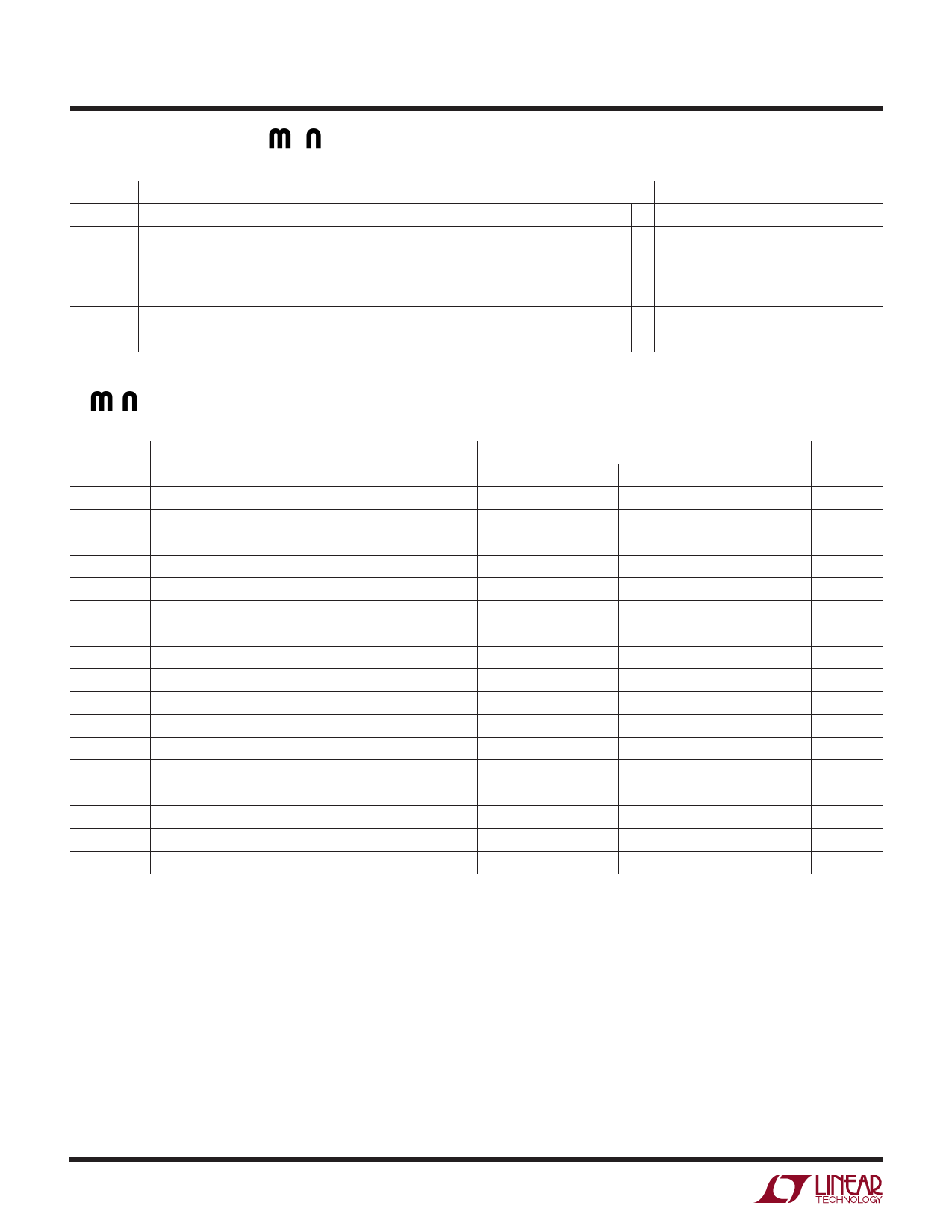
LTC1402
POWER REQUIRE E TS The q denotes the specifications which apply over the full operating temperature
range, otherwise specifications are at TA = 25°C. (Note 5)
SYMBOL
VDD
VSS
IDD
PARAMETER
Positive Supply Voltage
Negative Supply Voltage
Positive Supply Current
ISS
Negative Supply Current
PD
Power Dissipation
CONDITIONS
Active Mode
Nap Mode
Sleep Mode
Active, Sleep or Nap Modes with SCK Off
Active Mode with SCK in Fixed State (Hi or Lo)
MIN TYP MAX
4.75
5.25
– 5.25
0
q
18
30
q
3
5
2
10
q
2
90
150
UNITS
V
V
mA
mA
µA
µA
mW
WU
TI I G CHARACTERISTICS The q denotes the specifications which apply over the full operating temperature
range, otherwise specifications are at TA = 25°C. (Note 5)
SYMBOL
fSAMPLE(MAX)
tTHROUGHPUT
tSCK
tCONV
t0
t1
t2
t3
t4
t5
t6
t7
t8
t8a
t9
t10
t11
t12
PARAMETER
CONDITIONS
Maximum Sampling Frequency (Conversion Rate)
Minimum Sampling Period (Conversion + Acquisiton Period)
Minimum Clock Period
Conversion Time
(Note 9)
14th SCLK↑ to CONV↑ Interval
(Notes 9, 10, 16)
Minimum Positive or Negative SCK Pulse Width
(Note 9)
CONV to SCK Setup Time
(Notes 9, 13)
SCK After CONV
(Note 9)
Minimum Positive or Negative CONV Pulse Width
(Note 9)
SCK to Sample Mode
(Note 9)
CONV to Hold Mode
(Notes 9, 14)
Minimum Delay Between Conversions
(Note 9)
Minimum Delay from SCK to Valid Bits 0 Through 11
(Notes 9, 15)
Minimum Delay from SCK to Valid REFREADY
(Notes 9, 15)
SCK to Hi-Z at DOUT
Previous DOUT Bit Remains Valid After SCK
REFREADY Bit Delay After Sleep-to-Wake Transition
(Notes 9, 15)
(Notes 9, 15)
(Notes 9, 17)
VREF Settling Time After Sleep-to-Wake Transition
(Notes 9, 17)
MIN
q 2.2
q
q 28
q 57
q
q
q0
q
q
q
q 48
q
q
q
q4
q
q
TYP MAX
UNITS
MHz
455
ns
10000
ns
14
SCK cycles
ns
3.8
6
ns
7.3
12
ns
ns
3.5
5
ns
9
14
ns
3.4
5
ns
ns
9
12
ns
15
20
ns
11.4
16
ns
7
ns
10
ms
2
ms
Note 1: Absolute Maximum Ratings are those values beyond which the life
of a device may be impaired.
Note 2: All voltage values are with respect to ground with DGND, AGND1
and AGND2 wired together.
Note 3: When these pins are taken below VSS or above VDD, they will be
clamped by internal diodes. This product can handle input currents greater
than 100mA below VSS or greater than VDD without latchup.
Note 4: When these pins are taken below VSS, they will be clamped by
internal diodes. This product can handle input currents greater than
100mA below VSS or greater than VDD. These pins are not clamped to VDD.
Note 5: VDD = 5V, fSAMPLE = 2.2MHz, VSS = 0V for unipolar mode
specifications and VSS = – 5V for bipolar specifications.
Note 6: Linearity, offset and full-scale specifications apply for a single-
ended AIN+ input with AIN– grounded and using the internal reference in
bipolar mode with ±5V supplies.
Note 7: Integral linearity is defined as the deviation of a code from the
straight line passing through the actual endpoints of a transfer curve. The
deviation is measured from the center of quantization band.
Note 8: Bipolar offset is the offset measured from – 0.5LSB when the input
flickers between 1000 0000 0000 and 0111 1111 1111.
Note 9: Guaranteed by design, not subject to test.
Note 10: Recommended operating conditions.
Note 11: The analog input range is defined as the voltage difference
between AIN+ and AIN–. The bipolar ±2.048V input range could be used
with a single 5V supply if the absolute voltages of the inputs remain within
the single 5V supply voltage.
4
Share Link: 