OM4085T 데이터 시트보기 (PDF) - Philips Electronics
부품명
상세내역
제조사
OM4085T Datasheet PDF : 36 Pages
| |||
Philips Semiconductors
Universal LCD driver for low multiplex
rates
Product specification
OM4085
handbook, full pagewidth
BP0
BP1
Sn
Sn + 1
VDD
VDD − Vop/3
VDD − 2Vop/3
VLCD
VDD
VDD − Vop/3
VDD − 2Vop/3
VLCD
VDD
VDD − Vop/3
VDD − 2Vop/3
VLCD
VDD
VDD − Vop/3
VDD − 2Vop/3
VLCD
state 1
state 2
Vop
2Vop/3
Vop/3
0
−Vop/3
−2Vop/3
−Vop
Vop
2Vop/3
Vop/3
0
−Vop/3
−2Vop/3
−Vop
Tframe
LCD segments
state 1
state 2
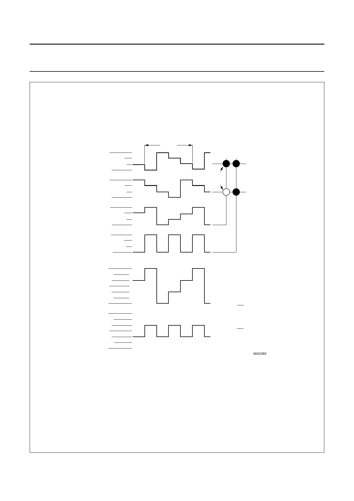
(a) waveforms at driver
(b) resultant waveforms
at LCD segment
At any instant (t):
Vstate 1(t) = VSn(t) − VBP0(t)
Von(rms) = Vop√5 = 0.745Vop
3
Vstate 2(t) = VSn(t) − VBP1(t)
Voff(rms) = Vop = 0.333Vop
3
MGG393
1997 Feb 25
Fig.6 Waveforms for 1 : 2 multiplex drive mode with 1⁄3 bias: Vop = VDD − VLCD.
9
Share Link: 