LA4550 데이터 시트보기 (PDF) - SANYO -> Panasonic
부품명
상세내역
제조사
LA4550 Datasheet PDF : 9 Pages
| |||
LA4550
Proper Cares in Using LA4550-Applied Set
1. If the transformer regulation is not as specified, the supply voltage drops momentarily when the motor of an AC-
powered set is turned ON. In this case, hum noise may be generated. So, be careful of the transformer regulation.
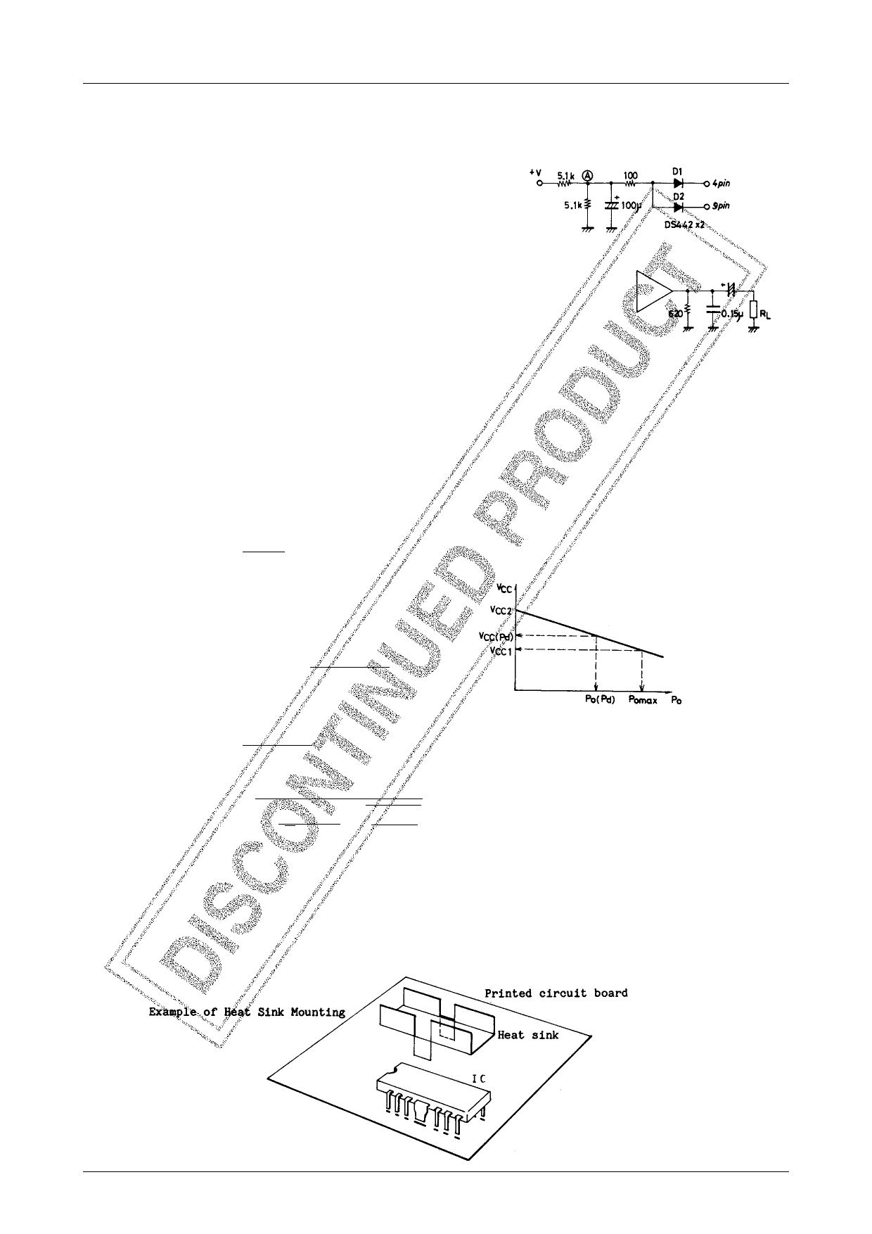
2. DC muting
To apply DC muting by controlling the NF pin, it is recommended
to use the circuit configuration shown right. The potential at point
(A) is set to 3.5 to 4V.
3. Pop noise
If pop noise generated at the time of power ON/OFF disturbs you, connect a resistor of approximately 620Ω across
the middle point and GND.
4. Slider contact noise of variable resistor
Since the input circuit uses PNP transistors, no input coupling capacitor is required.
However, if slider contact noise of the variable resistor presents any problem, connect a
capacitor in series with input.
Thermal Design
Since the DIP-12F package is such that the Cu-foiled area of the printed circuit board is used to dissipate heat, make the
Cu-foiled area in the vicinity of the heat sink of the IC as large as possible when designing the printed circuit board. The
use of the Cu-foiled area indicated by shading in the above-mentioned sample printed circuit pattern makes it possible
to dissipate more heat. Power dissipation Pd is increased depending on the supply voltage and load. So, it is recom-
mended to use the printed circuit board together with the heat sink. The following is a formula to be used to calculate Pd
(for stereo use). For AC power supply, however, it is recommended to actually measure Pd on the transformer of each
set. For bridge amplifier use, Pd is calculated at 1/2 of the load.
(1) DC power supply
Pd max=
VCC2
π2RL
+ Icco · VCC (For stereo use) ..... (1)
(2) AC power supply
VCC2 : Supply voltage at quiescent mode
VCC (Pd) : Supply voltage at Pd max
VCC1 : Supply voltage at maximum output
r
: Voltage regulation VCC2 – VCC1
VCC1
Icco : Quiescent current
Supply voltage regulation
Pd max=
VCC(Pd)2
π2RL
+ Icco · VCC (Pd)
(For stereo use) .............. (2)
where
VCC (Pd)=
(1+r) VCC1
√ 1+
r · VCC1
√2 · π · RL
×
RL
Po max
Example of Heat Sink Mounting Method
The heat sink must be of such a shape as to be able to dissipate heat from the IC plastic area and fin area and is soldered to
the printed circuit board as shown below. For the size of the heat sink, refer to the Pd – Ta characteristic. The material of the
heat sink is recommended to be copper or iron which is solderable. It is recommended to apply silicone grease to the IC
plastic area to reduce thermal resistance between the heat sink and the IC plastic area.
No.1718–5/9
Share Link: 