74ACTQ16646SSCX 데이터 시트보기 (PDF) - Fairchild Semiconductor
부품명
상세내역
제조사
74ACTQ16646SSCX Datasheet PDF : 9 Pages
| |||
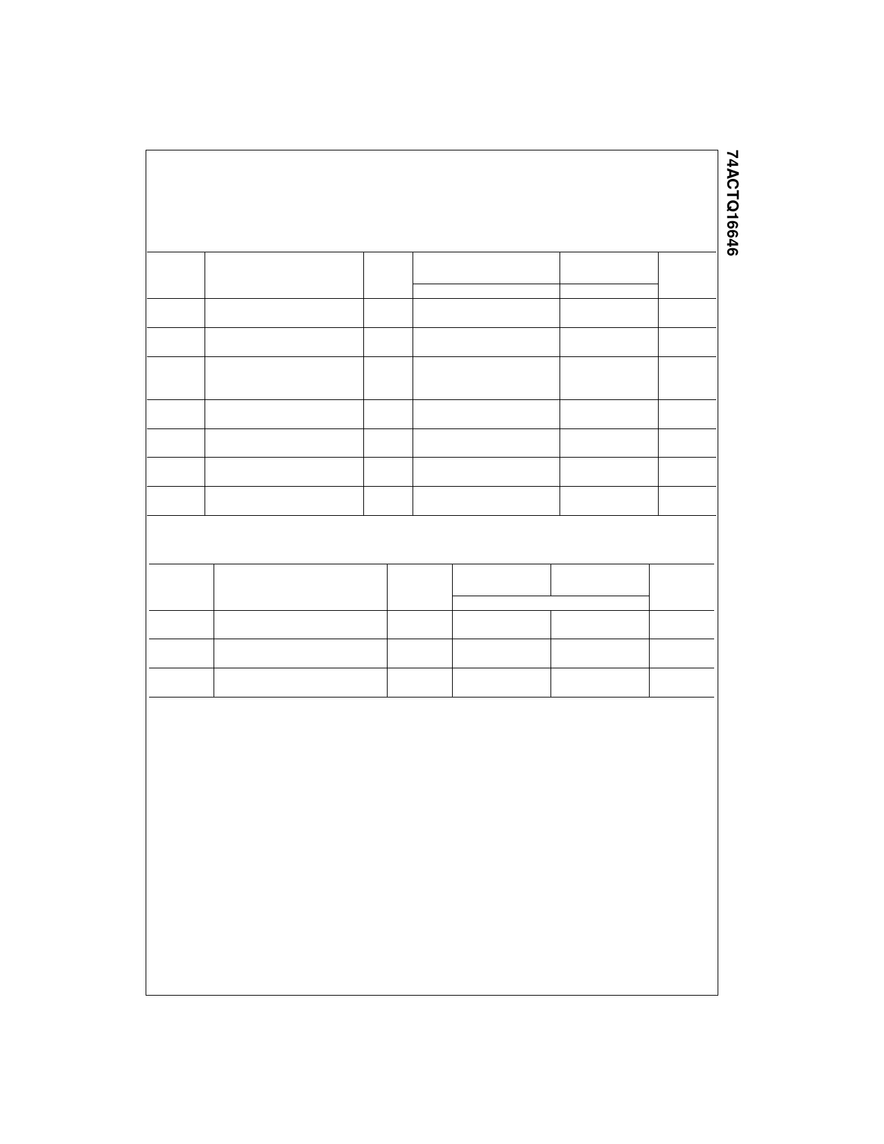
DC Electrical Characteristics (Continued)
Note 6: Maximum number of outputs that can switch simultaneously is n. (n − 1) outputs are switched LOW and one output held LOW.
Note 7: Maximum number of outputs that can switch simultaneously is n. (n − 1) outputs are switched HIGH and one output held HIGH.
Note 8: Maximum number of data inputs (n) switching. (n − 1) inputs switching 0V to 3V (ACTQ). Input under test switching 3V to threshold (VILD).
AC Electrical Characteristics
Symbol
Parameter
tPHL
Propagation Delay
tPLH
Clock to Bus
tPHL
Propagation Delay
tPLH
Bus to Bus
tPHL
Propagation Delay
tPLH
Select to Bus
(w/An or Bn HIGH or LOW)
tPZL
Enable Time
tPZH
G to An/Bn
tPLZ
Disable Time
tPHZ
G to An/Bn
tPZL
Enable Time
tPZH
DIR to An/Bn
tPLZ
Disable Time
tPHZ
DIR to An/Bn
Note 9: Voltage Range 5.0 is 5.0V ± 0.5V.
VCC
(V)
(Note 9)
5.0
5.0
5.0
5.0
5.0
5.0
5.0
TA = +25°C
CL = 50 pF
Min
Typ
Max
4.6
6.9
9.4
4.3
6.5
8.9
4.0
6.2
8.5
4.1
6.4
8.6
4.0
6.4
8.9
4.2
6.7
9.5
5.3
7.8
10.5
4.6
6.9
9.4
3.0
5.5
8.1
3.4
5.7
8.3
5.1
8.2
11.8
4.6
7.5
10.8
2.9
5.8
9.2
3.4
6.1
9.2
TA = −40°C to +85°C
CL = 50 pF
Min
Max
3.6
10.1
3.3
9.7
2.9
9.2
3.2
9.3
3.1
9.6
3.2
10.4
3.8
11.4
3.3
10.2
2.3
8.6
2.6
8.6
4.3
12.7
3.7
11.7
2.0
9.8
2.5
9.7
Units
ns
ns
ns
ns
ns
ns
ns
AC Operating Requirements
Symbol
Parameter
tS
Setup Time, H or L
Bus to Clock
tH
Hold Time, H or L
Bus to Clock
tW
Clock Pulse Width
H or L
Note 10: Voltage Range 5.0 is 5.0V ± 0.5V.
VCC
(V)
(Note 10)
5.0
5.0
5.0
TA = +25°C
TA = −40°C to +85°C
CL = 50 pF
CL = 50 pF
Guaranteed Minimum
3.0
3.0
1.5
1.5
4.0
4.0
Units
ns
ns
ns
5
www.fairchildsemi.com
Share Link: 