74F378 데이터 시트보기 (PDF) - Philips Electronics
부품명
상세내역
제조사
74F378 Datasheet PDF : 10 Pages
| |||
Philips Semiconductors
Hex D flip-flop with enable
Product specification
74F378
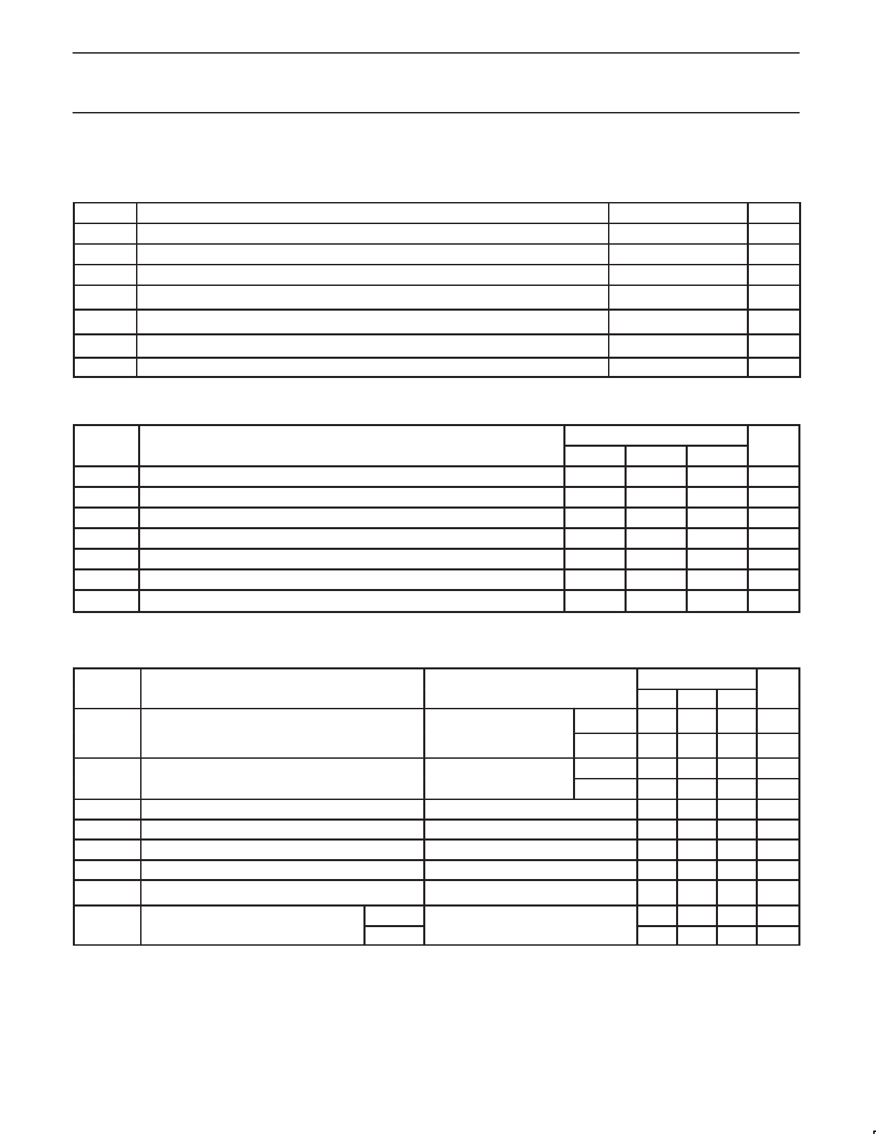
ABSOLUTE MAXIMUM RATINGS
(Operation beyond the limit set forth in this table may impair the useful life of the device. Unless otherwise noted these limits are over the
operating free-air temperature range.)
SYMBOL
PARAMETER
RATING
UNIT
VCC
VIN
IIN
VOUT
Supply voltage
Input voltage
Input current
Voltage applied to output in High output state
–0.5 to +7.0
V
–0.5 to +7.0
V
–30 to +5
mA
–0.5 to VCC
V
IOUT
Current applied to output in Low output state
40
mA
Tamb
Tstg
Operating free-air temperature range
Storage temperature range
0 to +70
°C
–65 to +150
°C
RECOMMENDED OPERATING CONDITIONS
SYMBOL
VCC
VIH
VIL
IIK
IOH
IOL
Tamb
Supply voltage
PARMETER
SYMBOL
High-level input voltage
Low-level input voltage
Input clamp current
High-level output current
Low-level output current
Operating free-air temperature range
LIMITS
UNIT
MIN
NOM
MAX
4.5
5.0
5.5
V
2.0
V
0.8
V
–18
mA
–1
mA
20
mA
0
70
°C
DC ELECTRICAL CHARACTERISTICS
(Over recommended operating free-air temperature range unless otherwise noted.)
SYMBOL
PARAMETER
TEST
CONDITIONS1
LIMITS
UNIT
MIN TYP2 MAX
VOH
High-level output voltage
VOL
Low-level output voltage
VIK
Input clamp voltage
II
Input current at maximum input voltage
IIH
High-level input current
IIL
Low-level input current
IOS
Short-circuit output current3
VCC = MIN, VIL = MAX,
VIH = MIN, IOH = MAX
VCC = MIN, VIL = MAX,
VIH = MIN, IOL = MAX
VCC = MIN, II = IIK
VCC = MAX, VI = 7.0V
VCC = MAX, VI = 2.7V
VCC = MAX, VI = 0.5V
VCC = MAX
±10%VCC 2.5
V
±5%VCC 2.7 3.4
V
±10%VCC
±5%VCC
0.30 0.50 V
0.30 0.50 V
–0.73 –1.2 V
100 µA
20 µA
–0.6 mA
–60
–150 mA
ICC
Supply current (total)
ICCH
ICCL
VCC = MAX
32 45 mA
35 45 mA
Notes:
1. For conditions shown as MIN or MAX, use the appropriate value specified under recommended operating conditions for the applicable type.
2. All typical values are at VCC = 5V, Tamb = 25°C.
3. Not more than one output should be shorted at a time. For testing IOS, the use of high-speed test apparatus and/or sample-and-hold
techniques are preferable in order to minimize internal heating and more accurately reflect operational values. Otherwise, prolonged shorting
of a High output may raise the chip temperature well above normal and thereby cause invalid readings in other parameter tests. In any
sequence of parameter tests, IOS tests should be performed last.
1989 Oct 05
4
Share Link: 