7MBR10SA-120 데이터 시트보기 (PDF) - Fuji Electric
부품명
상세내역
제조사
7MBR10SA-120 Datasheet PDF : 6 Pages
| |||
7MBR 10SA-120
IGBT PIM
1200V
6x10A+Chopper
I Electrical Characteristics( Tj=25°C )
Items
Zero Gate Voltage Collector Current
Gate-Emitter Leackage Current
Gate-Emitter Threshold Voltage
Collector-Emitter Saturation Voltage
Input Capacitance
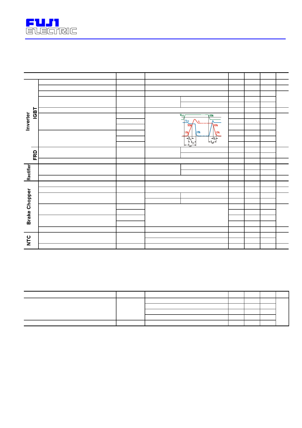
Turn-on Time
Turn-off Time
Symbols
ICES
IGES
VGE(th)
VCE(sat)
Cies
ton
tr,x
tr,i
toff
tf
Test Conditions
VGE=0V VCE=1200V
VCE=0V VGE=± 20V
VGE=20V IC=10mA
VGE=15V
Chip
IC = 10A
Terminal
f=1MHz, VGE=0V, VCE=10V
VCC = 600V
IC = 10A
VGE = ±15V
RG = 120Ω
Inductive Load
Diode Forward On-Voltage
Reverse Recovery Time
Forward Voltage
Reverse Current
Zero Gate Voltage Collector Current
Gate-Emitter Leackage Current
Collector-Emitter Saturation Voltage
Turn-on Time
Turn-off Time
Reverse Current
Resistance
B Value
VF
trr
VFM
IRRM
ICES
IGES
VCE(sat)
ton
tr,x
toff
tf
IRRM
R
B
IF=10A
Chip
Terminal
IF=10A
IF=10A
Chip
Terminal
VR =1600V
VGE=0V VCE=1200V
VCE=0V VGE=± 20V
VGE=10V
Chip
IC=10A
VCC = 600V
Terminal
IC = 10A
VGE = ±15V
RG = 120Ω
VR=1200V
T= 25°C
T=100°C
T=25 / 50°C
Min.
5.5
Typ.
7.2
2.1
2.15
1200
0.35
0.25
0.10
0.45
0.08
Max. Units
1.0 mA
200 nA
8.5
V
2.7
pF
1.2
0.6
1.0 µs
0.3
2.3
2.35 3.2
V
350 ns
1.1
1.2
1.5
V
1.0 mA
1.0 mA
200 nA
2.10
2.20 2.6
V
0.35 1.2
0.25 0.6
0.45 1.0
µs
0.08 0.3
1.0 mA
5000
465 495 520 Ω
3305 3375 3450 K
I Thermal Characteristics
Items
Thermal Resistance (1 device)
Contact Thermal Resistance
Symbols
Rth(j-c)
Rth(c-f)
Test Conditions
Inverter IGBT
Inverter FRD
Brake IGBT
Rectifier Diode
With Thermal Compound
Min.
Typ.
0.05
Max. Units
1.67
2.78
1.67 °C/W
1.85
Share Link: 