A25L16PMF-50 데이터 시트보기 (PDF) - AMIC Technology
부품명
상세내역
제조사
A25L16PMF-50 Datasheet PDF : 34 Pages
| |||
A25L80P
Table 1. Protected Area Sizes
Status Register Content
Memory Content
BP2 Bit BP1 Bit BP0 Bit
0
0
0
none
Protected Area
Unprotected Area
All sectors1 (sixteen sectors: 0 to 15)
0
0
0
1
0
1
1
Upper sixteenth (sector 15)
0
Upper eighth (two sectors: 14 and 15)
1
Upper quarter (four sectors: 12 to 15)
Lower fifteen-eighths (fifteen sectors: 0 to 14)
Lower seven-eights (fourteen sectors: 0 to 13)
Lower three-quarters (twelve sectors: 0 to 11)
1
0
1
0
1
1
0
Upper half (eight sectors: 8 to 15)
1
All sectors (eight sectors: 0 to 15)
0
All sectors (eight sectors: 0 to 15)
Lower half (eight sectors: 0 to 7)
none
none
1
1
1
All sectors (eight sectors: 0 to 15)
none
Note: 1. The device is ready to accept a Bulk Erase instruction if, and only if, all Block Protect (BP2, BP1, BP0) are 0.
Hold Condition
The Hold ( HOLD ) signal is used to pause any serial
communications with the device without resetting the clocking
sequence. However, taking this signal Low does not terminate
any Write Status Register, Program or Erase cycle that is
currently in progress.
To enter the Hold condition, the device must be selected, with
Chip Select ( S ) Low.
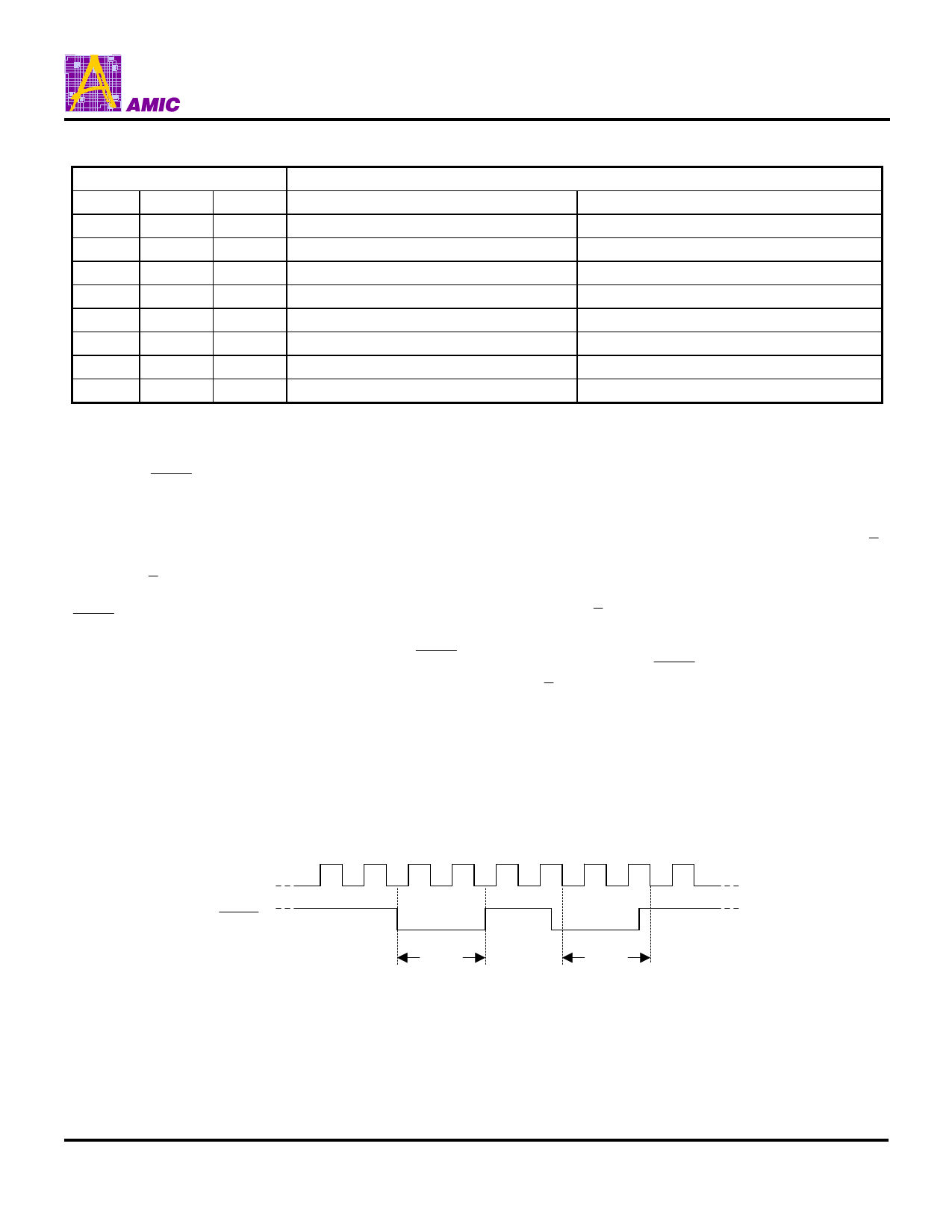
The Hold condition starts on the falling edge of the Hold
(HOLD ) signal, provided that this coincides with Serial Clock
(C) being Low (as shown in Figure 3.).
The Hold condition ends on the rising edge of the Hold ( HOLD )
signal, provided that this coincides with Serial Clock (C) being
Low.
If the falling edge does not coincide with Serial Clock (C) being
Low, the Hold condition starts after Serial Clock (C) next goes
Low. Similarly, if the rising edge does not coincide with Serial
Clock (C) being Low, the Hold condition ends after Serial Clock
(C) next goes Low. This is shown in Figure 3.
During the Hold condition, the Serial Data Output (Q) is high
impedance, and Serial Data Input (D) and Serial Clock (C) are
Don’t Care.
Normally, the device is kept selected, with Chip Select ( S )
driven Low, for the whole duration of the Hold condition. This is
to ensure that the state of the internal logic remains unchanged
from the moment of entering the Hold condition.
If Chip Select ( S ) goes High while the device is in the Hold
condition, this has the effect of resetting the internal logic of the
device. To restart communication with the device, it is
necessary to drive Hold ( HOLD ) High, and then to drive Chip
Select ( S ) Low. This prevents the device from going back to
the Hold condition.
Figure 3. Hold Condition Activation
C
HOLD
Hold
Condition
(standard use)
Hold
Condition
(non-standard use)
PRELIMINARY (May 2005, Version 0.0)
6
AMIC Technology Corp.
Share Link: 