A5338 데이터 시트보기 (PDF) - Allegro MicroSystems
부품명
상세내역
제조사
A5338 Datasheet PDF : 8 Pages
| |||
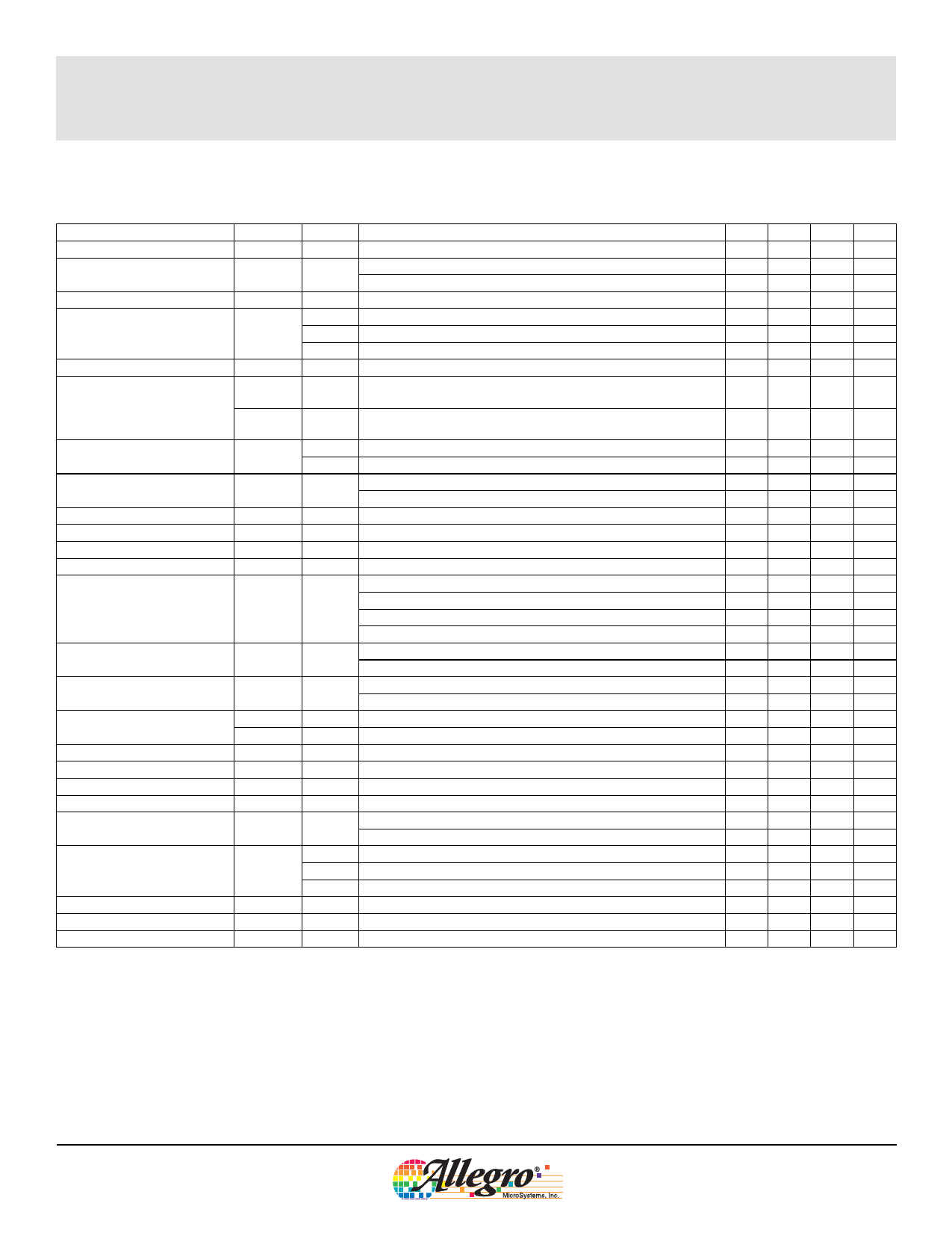
A5338 Smoke Detector with Interconnect and Timer
ELECTRICAL CHARACTERISTICS1 at TA = 25°C, VDD = 9.0 V, VSS = 0 V, COSC = 0.1 μF, RT = 8.2 MΩ, unless otherwise noted
Characteristic
Symbol Test Pin
Test Conditions
Min. Typ. Max. Units
Supply Voltage Range
Supply Current
Detector Input Current2
VDD
6 Operating
IDD
6
VDD = 9.0 V, no alarm, no loads
VDD = 12 V, no alarm, no loads
IS
15 0 to 40% RH, VI(detect in) = 0 to 9.0 V
14-15 Active guard
6.0 9.0 12 V
— 5.0 9.0 μA
— — 12 μA
–1.0 — 1.0 pA
–100 — 100 mV
Input Offset Voltage
VIO
16-15 Active guard
15-13 Smoke detect comparator
–100 —
–50 —
100 mV
50 mV
Hysteresis
Common Mode Range
VOhys
VIC(guard)
VIC(det)
13 No alarm condition to alarm
14-15 Guard amplifier
13-15 Smoke detect comparator
90 130 170 mV
2.0
—
VDD
- 0.5
V
0.5
—
VDD
- 2.0
V
Active Guard Impedance
Oscillator Period
Zguard
tOSC
14 With reference to VSS
16 With reference to VSS
No alarm
12 Alarm
— 10 — Ω
— 500 — Ω
1.34 1.67 2.00 s
32 40 48 ms
Oscillator Pulse Width
Timer Period
Low Voltage Threshold
Sensitivity Adjust Voltage
HORNx Output Voltage
HORNx Output ON Time
tw(osc)
ttimer
VDD(th)
VS
VO(horn)
ton(horn)
4
4
6
13
10-11
10-11
After VTIMER_START transition high-to-low (smoke detected)
TA = 0 to 50°C
VSENSITIVITY_SET/VDD, SENSITIVITY SET pin open circuit
IO(horn) = 16 mA, VDD = 9.0 V
IO(horn) = 16 mA, VDD = 7.2 V
IO(horn) = –16 mA, VDD = 9.0 V
IO(horn) = –16 mA, VDD = 7.2 V
Alarm
Low battery
8.0 10 12 ms
5.0 6.5 8.0 min
7.2 — 7.8 V
48.5 50 51.5 %
— 0.1 0.5 V
— — 0.9 V
8.5 8.8 —
V
6.3 —
—
V
120 160 208 ms
8.0 10 12 ms
HORNx Output OFF Time
toff(horn)
Alarm
10-11 Low Battery
60 80 104 ms
32 40 48
s
TIMER START Logic Levels
VIH(ts)
1
VIL(ts)
1
4.5 —
—
V
— — 2.5 V
TIMER START Input Current
II(ts)
1
VI(ts) = 9.0 V
20 — 80 μA
TIMER OUT Output Current
IO(to)
4
VO(to) = 0.5 V
500 — — μA
LED Output ON Current
ILED
5 VDD = 7.2 V, VLED = 1.0 V
10 — — mA
LED Output ON Time
ton(led)
5
8.0 10 12 ms
LED Output OFF Time
toff(led)
No alarm; in Standby mode
32 40 48
s
5
No alarm; in Timer mode after VTIMER_START transition high-to-low 8.0 10 12
s
2 No alarm, V(IO) = VDD - 2.0 V
25 — 60 μA
I/O Current2
I(io)
Alarm, V(IO) = VDD - 2.0 V
-7.5 — — mA
Charge dump, V(io) = 1.0 V
5.0 — — mA
I/O Charge Dump Duration
tf(io)
2 After local alarm
1.33 1.66 1.99 s
I/O Alarm Voltage
VI(io)
2 External alarm signal in
3.0 —
—
V
I/O Delay
td(io)
2 Alarm signal out
— 3.0 —
s
1Alarm (smoke detected) condition is defined as VDETECT_IN < VSENSITIVITY_SET; No-Alarm (no smoke detected) condition is defined as
VDETECT_IN > VSENSITIVITY_SET.
2Negative current is defined as coming out of (sourcing) the specified device pin.
26110.1
Allegro MicroSystems, Inc.
4
115 Northeast Cutoff, Box 15036
Worcester, Massachusetts 01615-0036 (508) 853-5000
www.allegromicro.com
Share Link: 