A8287 데이터 시트보기 (PDF) - Allegro MicroSystems
부품명
상세내역
제조사
A8287 Datasheet PDF : 17 Pages
| |||
A8285/A8287
LNB Supply and Control Voltage Regulator
SDA line before the ninth clock cycle, in order to allow this
handshaking to occur.
During a data read, the A8285/A8287 acknowledges the
address in the same way as in the data write sequence, and
then retains control of the SDA line and send the data to the
master. On completion of the eight data bits, the A8285/
A8287 releases the SDA line before the ninth clock cycle,
in order to allow the master to acknowledge the data. If the
master holds the SDA line low during this Acknowledge bit,
the A8285/A8287 responds by sending another data byte to
the master. Data bytes continue to be sent to the master until
the master releases the SDA line during the Acknowledge bit.
When this is detected, the A8285/A8287 stops sending data
and waits for a stop signal.
Interrupt Request. The A8285/A8287 also provides an
interrupt request pin IRQ, which is an open-drain, active-
low output. This output may be connected to a common
IRQ line with a suitable external pull-up and can be used
with other I2C devices to request attention from the master
controller. The IRQ output becomes active when either the
A8285/A8287 first recognizes a fault condition, or at power-
on when the main supply VIN and the internal logic supply
VREG reach the correct operating conditions. It is only reset
to inactive when the I2C master addresses the A8285/A8287
with the Read/Write bit set (causing a read). Fault conditions
are indicated by the TSD, VUV, and OCP bits in the status
register (see description of OCP for conditions of use). The
DIS and PNG bits do not cause an interrupt. When the mas-
ter recognizes an interrupt, it addresses all slaves connected
to the interrupt line in sequence, and then reads the status
register to determine which device is requesting attention.
The A8285/A8287 latches all conditions in the status regis-
ter until the completion of the data read.
The action at the resampling point is further defined in the
description for each of the status bits. The bits in the status
register are defined such that the all-zero condition indicates
that the A8285/A8287 is fully active with no fault conditions.
When VIN is initially applied, the I2C interface does not
respond to any requests until the internal logic supply VREG
has reached its operating level. Once VREG has reached this
point, the IRQ output goes active, and the VUV bit is set.
After the A8285/A8287 acknowledges the address, the IRQ
flag is reset. Once the master reads the status registers, the
registers are updated with the VUV reset.
Control Register (I2C Write Register). All main func-
tions of the A8285/A8287 are controlled through the I2C
interface via the 8-bit Control register. This register allows
selection of the output voltage and current limit, enabling and
disabling the LNB output, and switching the 22 kHz tone on
and off. The power-up state is 0 for all of the control functions.
Bit 0 (VSEL0), Bit 1 (VSEL1), and Bit 2 (VSEL2). These
provide incremental control over the voltage on the LNB
output. The available voltages provide the necessary levels
for all the common standards plus the ability to add line
compensation in increments of 333 mV. The voltage levels
are defined in the Output Voltage Amplitude Selection table.
Bit 3 (VSEL3). Switches between the low-level and high-
level output voltages on the LNB output. A value of 0 selects
the low level voltage and a value of 1 selects the high level.
The low-level center voltage is 12.709 V nominal, and the
high level is 18.042 V nominal. These may be increased, in
increments of 333 mV, by using the VSEL2, VSEL1, and
VSEL0 control register bits.
Bit 4 (ODT). When set to 1, enables the ODT feature
(disables the A8285/A8287 if the overcurrent disable time
is exceeded during an overcurrent condition on the output).
When set to 0, the ODT feature is disabled.
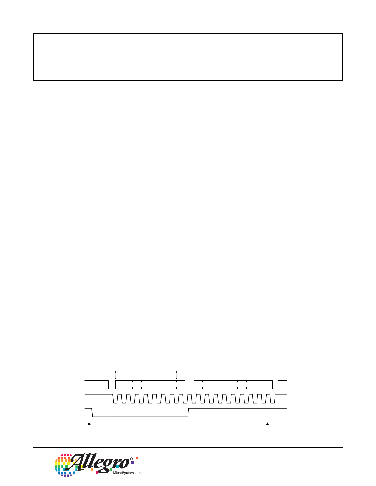
Reading the Register After an Interrupt
Start
Address
R
Status Data
Stop
SDA
0 0 0 1 0 A1 A0 1 AK D7 D6 D5 D4 D3 D2 D1 D0 NAK
SCL
123456789
IRQ
Fault
Event
Reload
Status Register
9
www.allegromicro.com
115 Northeast Cutoff, Box 15036
Worcester, Massachusetts 01615-0036 (508) 853-5000
Share Link: 