ACPL-7900 데이터 시트보기 (PDF) - Avago Technologies
부품명
상세내역
제조사
ACPL-7900 Datasheet PDF : 13 Pages
| |||
Definitions
Gain
Gain is defined as the slope of the best-fit line of differ-
ential output voltage (VOUT+ – VOUT–) vs. differential input
voltage (VIN+ – VIN–) over the nominal input range, with
offset error adjusted out.
Nonlinearity
Nonlinearity is defined as half of the peak-to-peak output
deviation from the best-fit gain line, expressed as a per-
centage of the full-scale differential output voltage.
Input DC Common Mode Rejection Ratio, CMRRIN
CMRRIN is defined as the ratio of the differential signal
gain (signal applied differentially between pins VOUT+ and
VOUT–) to the input side common-mode gain (input pins
tied together and the signal applied to both inputs with
respect to pin GND1), expressed in dB.
Common Mode Transient Immunity, CMTI, also known as
Common Mode Rejection
CMTI is tested by applying an exponentially rising/falling
voltage step on pin 4 (GND1) with respect to pin 5 (GND2).
The rise time of the test waveform is set to approximately
50 ns. The amplitude of the step is adjusted until the dif-
ferential output (VOUT+ – VOUT–) exhibits more than a 200
mV deviation from the average output voltage for more
than 1 Ps. The ACPL-790B/790A/7900 will continue to
function if more than 10 kV/Ps common mode slopes are
applied, as long as the breakdown voltage limitations are
observed.
Power Supply Rejection, PSR
PSR is the ratio of differential amplitude of the ripple
outputs over power supply ripple voltage, referred to the
input, expressed in dB.
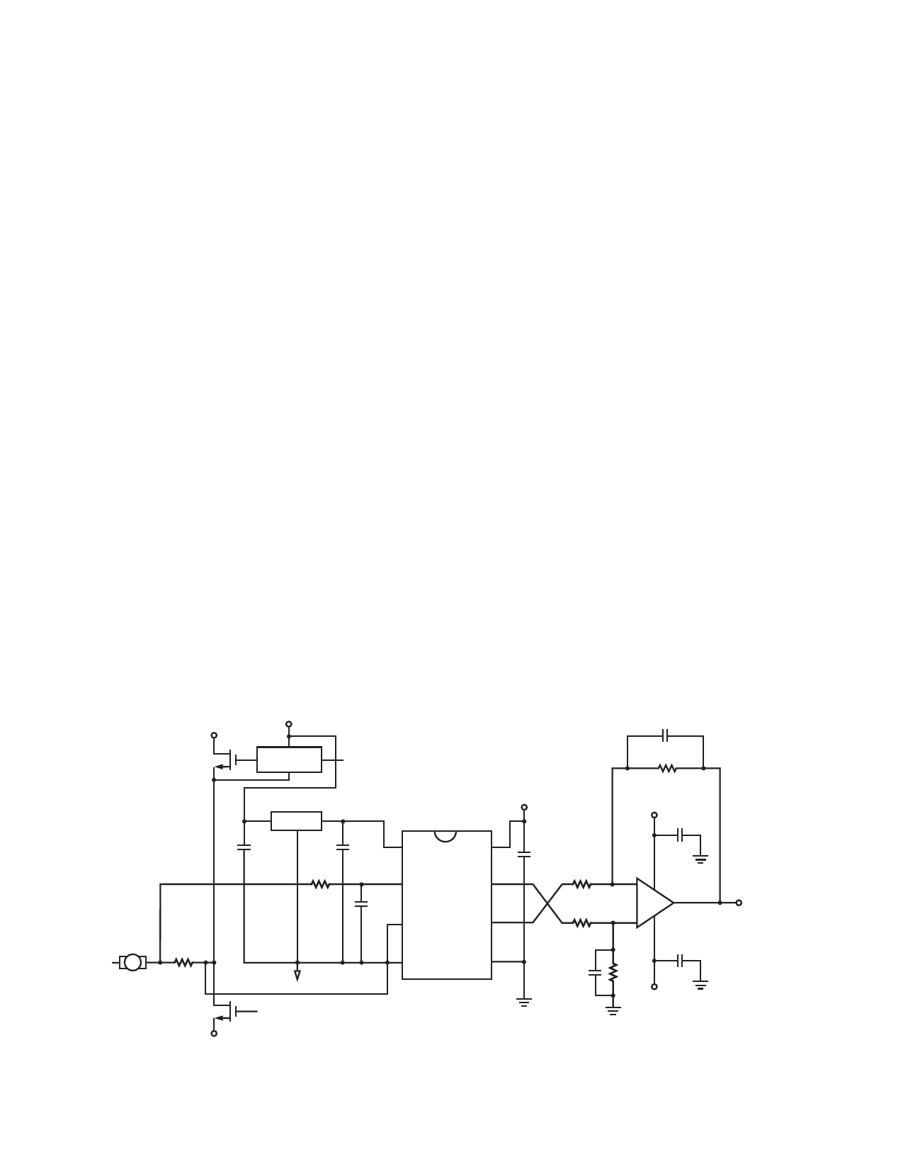
Application Information
Application Circuit
The typical application circuit is shown in Figure 21. A
floating power supply (which in many applications could
be the same supply that is used to drive the high-side
power transistor) is regulated to 5 V using a simple three-
terminal voltage regulator (U1). The voltage from the
current sensing resistor, or shunt (RSENSE), is applied to
the input of the ACPL-790B/790A/7900 through an RC
anti-aliasing filter (R5 and C3). And finally, the differential
output of the isolation amplifier is converted to a ground-
referenced single-ended output voltage with a simple dif-
ferential amplifier circuit (U3 and associated components).
Although the application circuit is relatively simple, a few
recommendations should be followed to ensure optimal
performance.
POSITIVE
FLOATING
SUPPLY
C5
HV+
68 pF
MOTOR + –
***
RSENSE
GATE DRIVE
CIRCUIT
***
R3
10.0 K
U1
78L05 VDD1
IN OUT
VDD2 (+5 V)
+15 V
C8
0.1 PF
C1
C2
1
8 C4
0.1
0.1
PF
R5 PF
2
0.1 PF
7
R1
GND2
10
C3
U2
47 nF 3
6
2.00 K
R2
–
U3
+ TL032A
VOUT
GND1
***
2.00 K
4
5
C7
C6
68 pF
R4
10.0 K
0.1 PF
ACPL-790B/
ACPL-790A/
-15 V GND2
ACPL-7900
GND2
GND2
HV-
Figure 21. Typical application circuit for motor phase current sensing.
11
Share Link: 