AD590JRZ-RL 데이터 시트보기 (PDF) - Analog Devices
부품명
상세내역
제조사
AD590JRZ-RL Datasheet PDF : 16 Pages
| |||
AD590
GENERAL APPLICATIONS
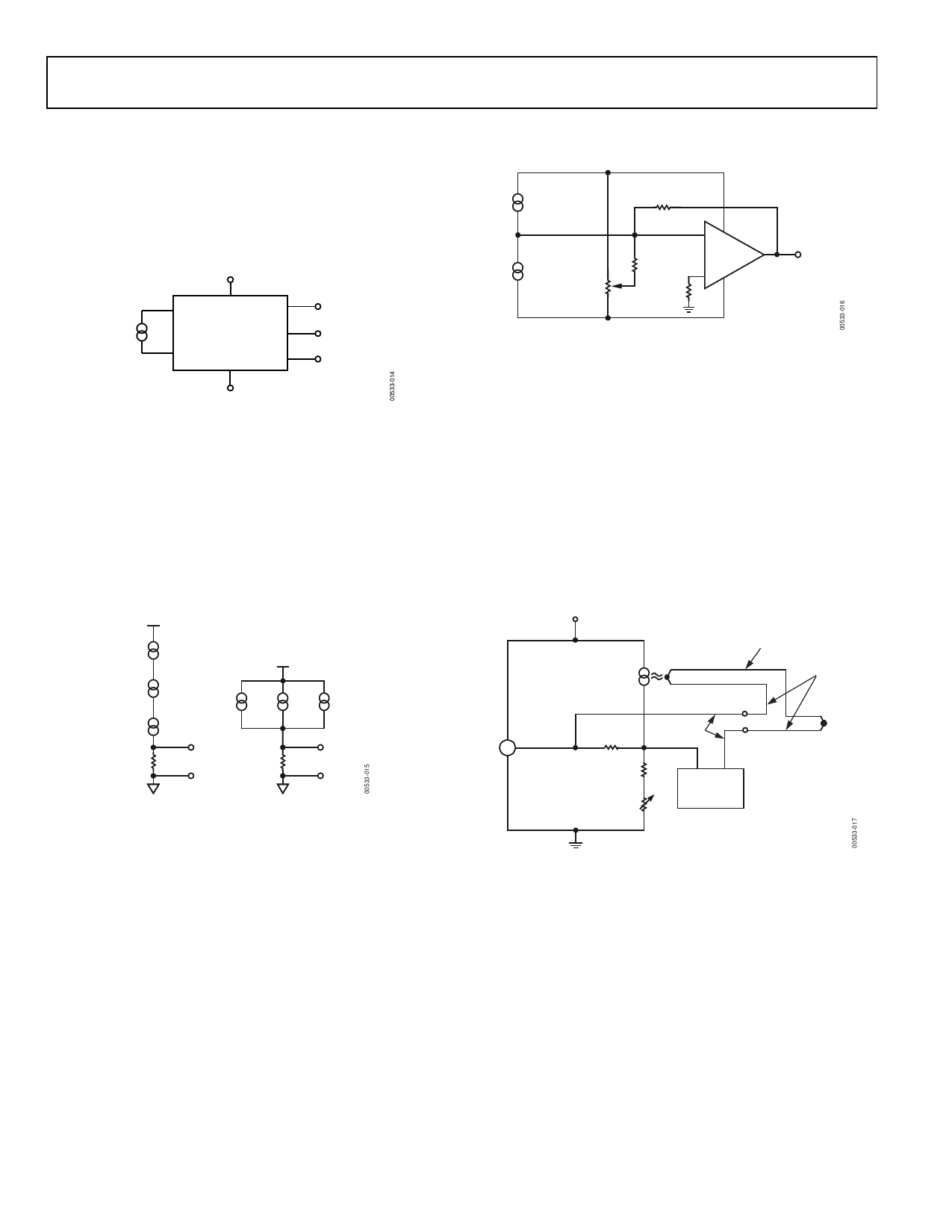
Figure 16 demonstrates the use of a low cost digital panel meter
for the display of temperature on either the Kelvin, Celsius, or
Fahrenheit scales. For Kelvin temperature, Pin 9, Pin 4, and
Pin 2 are grounded; for Fahrenheit temperature, Pin 4 and Pin 2
are left open.
5V
6
8
9
+
AD590
–
AD2040
4
5
3
2
OFFSET
CALIBRATION
GAIN
SCALING
OFFSET
SCALING
GND
Figure 16. Variable Scale Display
The above configuration yields a 3-digit display with 1°C or 1°F
resolution, in addition to an absolute accuracy of ±2.0°C over
the −55°C to +125°C temperature range, if a one-temperature
calibration is performed on an AD590K, AD590L, or AD590M.
Connecting several AD590 units in series, as shown in Figure 17,
allows the minimum of all the sensed temperatures to be
indicated. In contrast, using the sensors in parallel yields the
average of the sensed temperatures.
15V
10kΩ
(0.1%)
+
AD590
–
+
AD590
–
+
AD590
–
+
VT MIN
–
5V
+
+
–
–
+
AD590
–
333.3Ω
(0.1%)
+
VT AVG
–
Figure 17. Series and Parallel Connection
The circuit in Figure 18 demonstrates one method by which
differential temperature measurements can be made. R1 and R2
can be used to trim the output of the op amp to indicate a
desired temperature difference. For example, the inherent offset
between the two devices can be trimmed in. If V+ and V− are
radically different, then the difference in internal dissipation
causes a differential internal temperature rise. This effect can be
used to measure the ambient thermal resistance seen by the
sensors in applications such as fluid-level detectors or anemometry.
+
AD590L
– #2
V+
R3
10kΩ
+
AD590L
– #1
R2
50kΩ
R1
5MΩ
R4
10kΩ
–
AD707A
+
(T1 – T2) × (10mV/°C)
V–
Figure 18. Differential Measurements
Figure 19 is an example of a cold junction compensation circuit
for a Type J thermocouple using the AD590 to monitor the
reference junction temperature. This circuit replaces an ice-bath
as the thermocouple reference for ambient temperatures
between 15°C and 35°C. The circuit is calibrated by adjusting RT
for a proper meter reading with the measuring junction at a
known reference temperature and the circuit near 25°C. Using
components with the TCs as specified in Figure 19, compensation
accuracy is within ±0.5°C for circuit temperatures between
15°C and 35°C. Other thermocouple types can be accommodated
with different resistor values. Note that the TCs of the voltage
reference and the resistors are the primary contributors to error.
7.5V
+ AD580
– VOUT
+
AD590
–
52.3Ω
8.66kΩ
RT
1kΩ
REFERENCE
JUNCTION
+
–
CU
+–
METER
IRON
CONSTANTAN
MEASURING
JUNCTION
RESISTORS ARE 1%, 50ppm/°C
Figure 19. Cold Junction Compensation Circuit for Type J Thermocouple
Rev. E | Page 10 of 16
Share Link: 