LH1687 데이터 시트보기 (PDF) - Sharp Electronics
부품명
상세내역
제조사
LH1687 Datasheet PDF : 21 Pages
| |||
LH1687
FUNCTIONAL OPERATIONS OF EACH BLOCK
BLOCK
FUNCTION
Control Logic
Used to create signals necessary for each operation mode setting and sampling signal
creation circuits, etc.
Bi-directional Shift
Register
Used as transfer circuit of video sampling start signals.
It is possible to set the direction of sampling start signal sequence OS1/OS240 or
OS240/OS1 by setting the R/L pin.
Sampling Signal
Used to create the sampling signals corresponding to each output pin based on the
Creation Circuit
sampling start signals transferred by the bi-directional shift register.
Mode Setting Circuit Used to set the form of the video signals to be sent to the sample and hold circuits.
Sample and Hold
Used to sample the video signals input from the mode setting circuit at the timing of the
Circuit
sampling signals and hold the sampling data until the next sampling operation.
Bias Generation Circuit Used to generate bias voltage necessary for output circuits.
Output Circuit
The circuit consists of a push-pull output operational amplifier and outputs the voltage
corresponding to the data held in the sample and hold circuits.
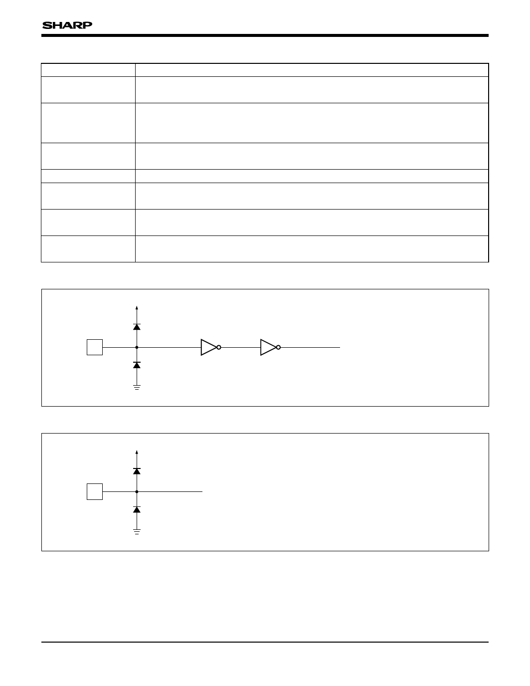
INPUT/OUTPUT CIRCUITS
VCCL
I
GNDL
Fig. 1 Input Circuit (1)
To Internal Circuit
¿Applicable pins¡
CK, CTR, MODE
VCCA
I
To Internal Circuit
GNDA
Fig. 2 Input Circuit (2)
¿Applicable pins¡
VA, VB, VC
4
Share Link: 