ADL5323 데이터 시트보기 (PDF) - Analog Devices
부품명
상세내역
제조사
ADL5323 Datasheet PDF : 12 Pages
| |||
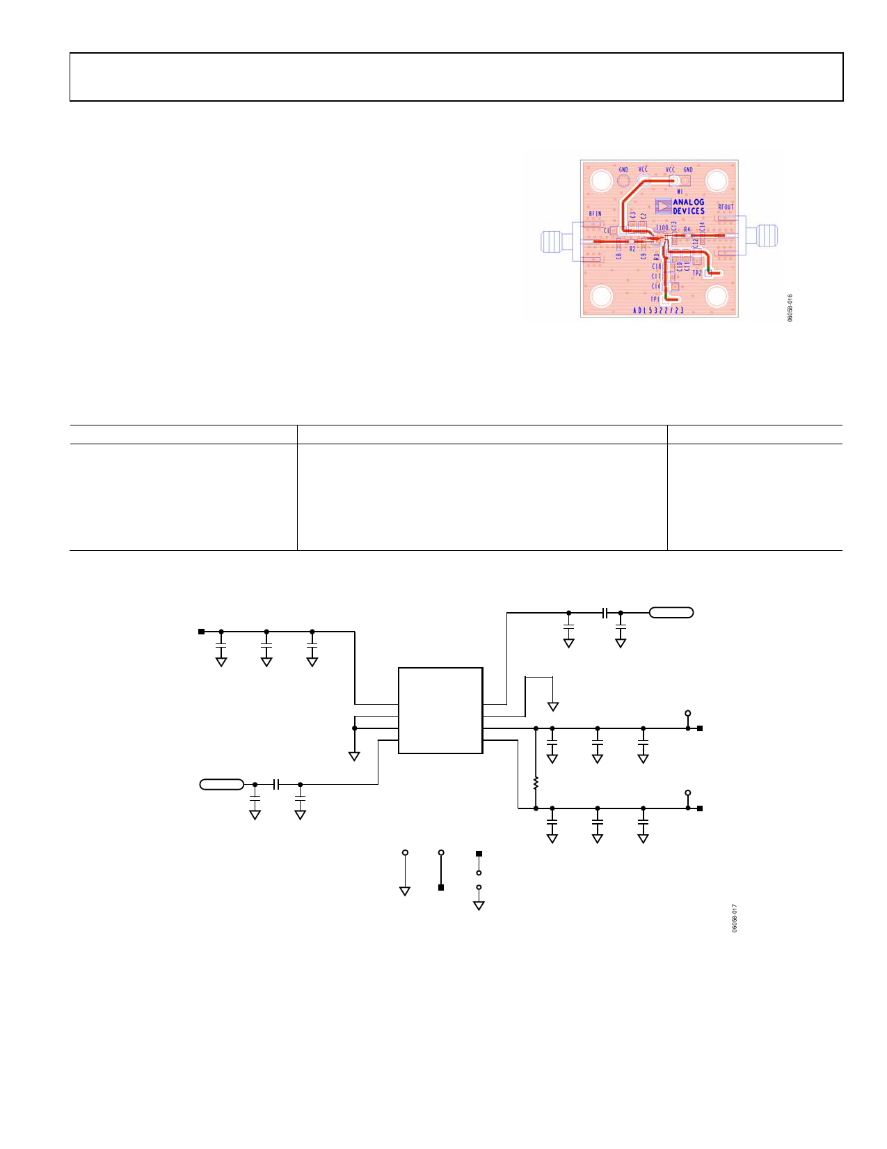
EVALUATION BOARD
Figure 18 shows the schematic of the ADL5323 evaluation
board. The board is powered by a single supply in the 4.75 V to
5.25 V range. The power supply is decoupled on each of the
three power supply pins by 10 μF, 10 nF, and 100 pF capacitors.
See Table 5 for the exact evaluation board component values.
Note that all three VCC pins (Pin 1, Pin 2, and Pin 5) should be
independently bypassed as shown in Figure 18 for proper
operation.
ADL5323
Figure 17. Evaluation Board Component Side View
Table 5. Evaluation Board Components
Component
Function
DUT1
Driver amplifier
C1, C12, C16
Low frequency bypass capacitors
C3, C11, C17
Low frequency bypass capacitors
C2, C10, C18
High frequency bypass capacitors
C8, C9, C13, C14, R3
Open
R2, R4
AC coupling capacitors
Default Value
ADL5323
10 μF, 0603
10 nF, 0402
100 pF, 0402
Open , 0402
100 pF, 0402
VCC
RFIN
C1
10µF
AGND
C3
10nF
AGND
C2
100pF
AGND
R2
100pF
AGND
C8
OPEN
AGND
C9
OPEN
AGND
ADL5322/
ADL5323
5 VCC
6 GND
7 GND
RFOUT 4
GND 3
VCC 2
8 RFIN
VCC 1
DUT1
GND VCC VCC
AGND
W1
VCC
AGND
R4
100pF
C13
OPEN
AGND
C14
OPEN
AGND
RFOUT
AGND
C10
100pF
AGND
R3
OPEN
C11
10nF
AGND
C18
100pF
AGND
C17
10nF
AGND
TP2
C12
10µF
AGND
VCC
TP1
SNS1
C16
10µF
AGND
VCC
Figure 18. Evaluation Board Schematic
Rev. 0 | Page 9 of 12
Share Link: 