ADM709-15 데이터 시트보기 (PDF) - Analog Devices
부품명
상세내역
제조사
ADM709-15 Datasheet PDF : 5 Pages
| |||
ADM709
VCC
VTH
ADM709
RESET
GENERATOR
RESET
GND
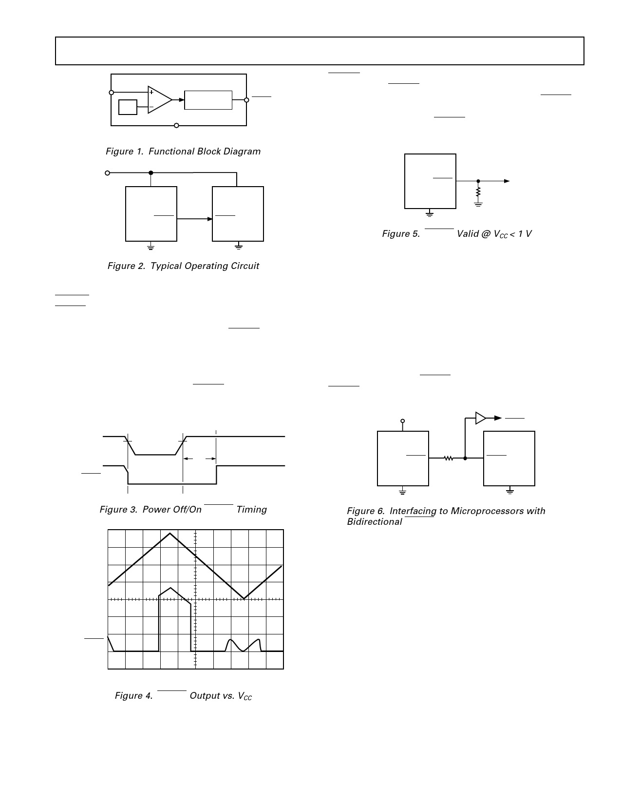
Figure 1. Functional Block Diagram
VCC
ADM709
RESET
GND
VCC
µP
RESET
GND
Figure 2. Typical Operating Circuit
CIRCUIT INFORMATION
RESET Output
RESET is an active low output which provides a reset signal to
the microprocessor whenever the VCC supply voltage is below
the reset threshold. An internal timer holds RESET low for
140 ms after the voltage on VCC rises above the threshold. This
is intended as a power-on reset signal for the processor. It allows
time for the power supply and microprocessor to stabilize after
power up. Similarly a power supply brownout will initiate a pro-
cessor reset. On power-down, the RESET output remains low
with VCC as low as 1 V. This ensures that the microprocessor is
held in a stable shutdown condition as the power supply drops.
VCC
RESET
VRT
VRT
tRS
RESET at Voltages < 1 V
The ADM709 RESET output is guaranteed to operate with
supply voltages as low as 1 V. If it is desired that the RESET
output remains low below 1 V, then a pull-down resistor should
be connected between the RESET output and GND. A resistor
of 100 kΩ is suitable. This is illustrated in Figure 5.
ADM709
RESET
R1
GND
Figure 5. RESET Valid @ VCC < 1 V
Glitch Immunity
The ADM709 is immune to short transients which may occur
on the VCC line. This is important so that spurious resets are not
generated as a result of minor glitches on the power supply.
Additional glitch immunity may be obtained by connecting a
capacitor (0.1 µF or greater) as close as possible to the VCC pin
on the device.
Microprocessors with Bidirectional I-O
Some microprocessors or microcontrollers such as the
MC68HC11 have bidirectional reset lines. In order to avoid
signal contention, a resistor of 4.7 kΩ should be connected
between the ADM709 RESET output and the microcontroller
RESET line. This arrangement is shown in Figure 6.
+5V
VCC
ADM709
RESET
BUFFERED
RESET
µP
RESET
GND
GND
Figure 3. Power Off/On RESET Timing
Figure 6. Interfacing to Microprocessors with
Bidirectional RESET
VCC
RESET
400ms/DIV
Figure 4. RESET Output vs. VCC
REV. 0
–3–
Share Link: 