ADM8843 데이터 시트보기 (PDF) - Analog Devices
부품명
상세내역
제조사
ADM8843 Datasheet PDF : 16 Pages
| |||
Data Sheet
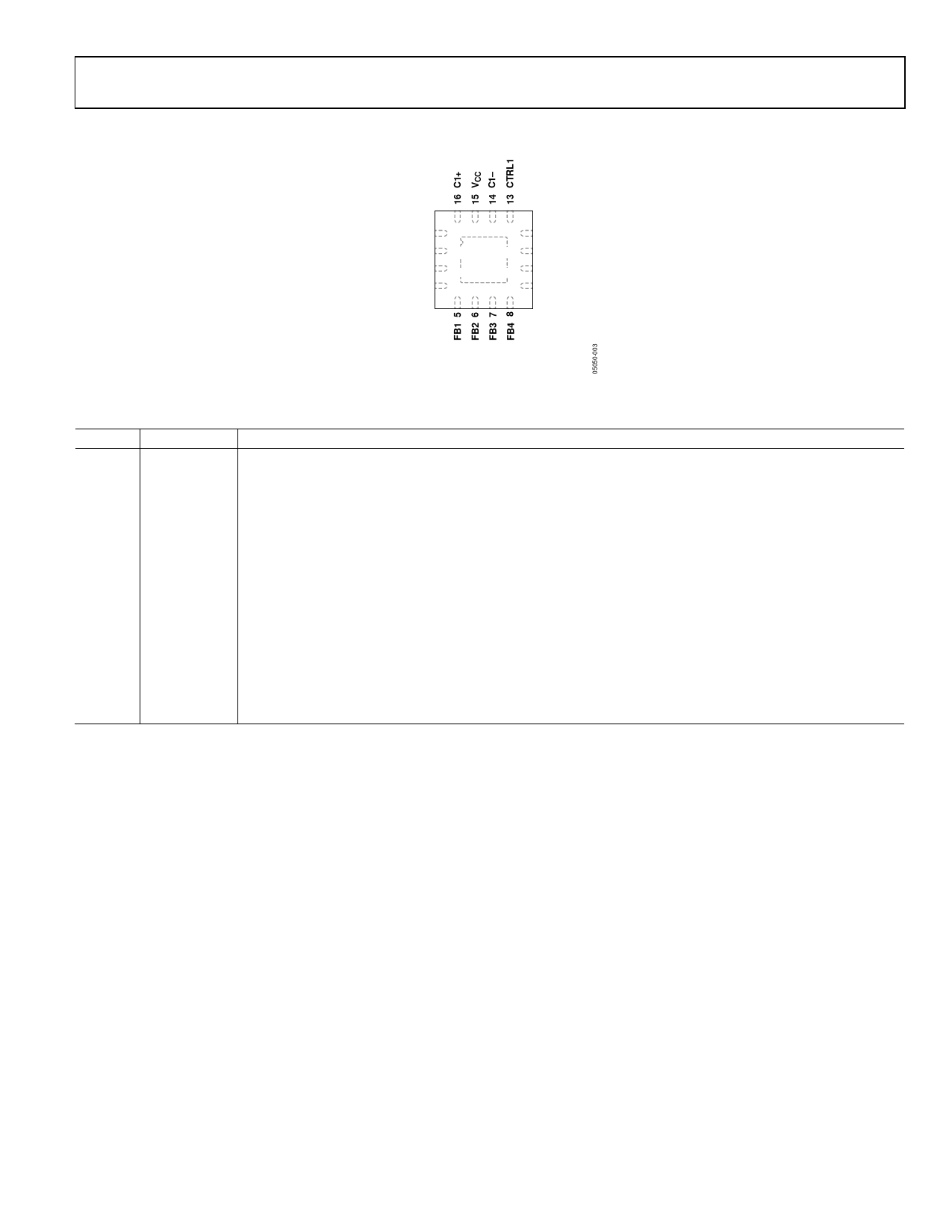
PIN CONFIGURATION AND FUNCTION DESCRIPTIONS
ADM8843
VOUT 1
C2+ 2
ISET 3
GND 4
ADM8843
TOP VIEW
(Not to Scale)
12 CTRL2
11 C2–
10 GND
9 GND
NOTES
1. CONNECT THE EXPOSED PADDLE TO GND.
Figure 2. Pin Configuration
Table 4. Pin Function Descriptions
Pin No. Mnemonic Description
1
VOUT
Charge Pump Output. A 2.2 µF capacitor to ground is required on this pin. Connect VOUT to the anodes of all the LEDs.
2
C2+
Flying Capacitor 2 Positive Connection.
3
ISET
Bias Current Set Input. The current flowing through the RSET resistor, ISET, is gained up by 120 to provide the ILED
current. Connect a resistor, RSET, to GND to set the bias current as VSET/RSET. Note that VSET = 1.18 V.
4, 9, 10 GND
Device Ground Pins.
5 to 8 FB1 to FB4
LED1 to LED4 Cathode Connection and Charge Pump Feedback. The current flowing in these LEDs is 120 times
the current flowing through RSET, ISET. When using fewer than four LEDs, this pin can be left unconnected or
connected to GND.
11
C2−
Flying Capacitor 2 Negative Connection.
12
CTRL2
Digital Input. 3 V CMOS Logic. Used with CTRL1 to control the shutdown operation of the main and sub LEDs.
13
CTRL1
Digital Input. 3 V CMOS Logic. Used with CTRL2 to control the shutdown operation of the main and sub LEDs.
14
C1−
Flying Capacitor 1 Negative Connection.
15
VCC
Positive Supply Voltage Input. Connect this pin to a 2.6 V to 5.5 V supply with a 4.7 µF decoupling capacitor.
16
C1+
Flying Capacitor 1 Positive Connection.
–
EP
Expose Paddle. Connect the exposed paddle to GND.
Rev. E | Page 5 of 16
Share Link: 