ADNS-7700-H4MY 데이터 시트보기 (PDF) - Avago Technologies
부품명
상세내역
제조사
ADNS-7700-H4MY Datasheet PDF : 60 Pages
| |||
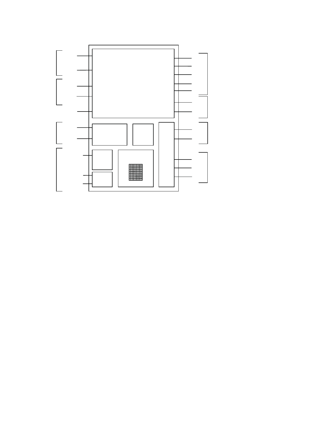
Block Diagram
D+
USB
PORT
D
ZA
Z-WHEEL
ZB
REFC
OSC_IN
OSCILLATOR OSC_OUT
LASER_GND
LASER
VCSEL +VE
VCSEL VE
CONTROL AND
I/O PROCESSOR
OSCILLATOR
POWER
ON
R
RESET
VE
OG
LU
LASER
DRIVE
IMAGE
TL
PROCESSOR
AA
GT
EO
R
VCSEL
B1
B2
B3 BUTTONS
B4
B5
TW1 TILT WHEEL*
TW2
REFA VOLTAGE
REFERENCE
REFB
VDD5
DGND
AGND
5-VOLT
USB VBUS
POWER
Figure 7. ADNS-7700 Block Diagram
Eye Safety
ADNS-7700 sensor and the associated components in
the schematic of Figure 6 are intended to comply with
Class 1 Eye Safety requirements of IEC/EN 60825-1. Avago
Technologies calibrate sensor laser output power (LOP)
to Class 1 eye safety level prior shipping out, thus no laser
output power calibration is required at mouse manufac-
turer site.
ADNS-7700 sensor is designed to maintain the laser
output power using ADNS-6180-002 lens within Class 1
requirements over components manufacturing toleranc-
es under the recommended operating conditions and ap-
plication circuit of Figure 6 as specified in this document.
Under normal operating conditions, the sensor gener-
ates the drive current for the VCSEL. Increasing the LOP
by other means on hardware and software can result in a
violation of the Class 1 eye safety limit of 716 W. For more
information, please refer to Eye Safety Application Note.
Laser Output Power
The laser output power,LOP can be measured at the navi-
gation surface plane. The sensor can drive the laser in
continuous (CW) mode by writing to LSR_CTRL0 and LSR_
CTRL1 registers via USB Set Vendor test command.
The pre-calibrated LOP value at typical operating supply
voltage and temperature of 25 ± 5°C should not exceed-
ing 506W, otherwise the LOPmax limit in the Absolute
Maximum Rating is applicable.
The following conditions apply:
1. The system is operated based on the recommended
application circuit in Figure 6 and within the recom-
mended operating conditions.
2. Measurement is taken at the optical center and illumi-
nation angle on navigation surface plane, Z.
3. No allowance for optical power meter accuracy is
assumed.
Single Fault Detection
ADNS-7700 sensor is able to detect a short circuit or fault
condition at the -VCSEL pin, which could lead to exces-
sive laser power output. A path to ground on this pin will
trigger the fault detection circuit, which will turn off the
laser drive current source and set the LASER_NEN output
high. The system will prevent excess laser power for a re-
sistive path to ground at -VCSEL by shutting off the laser.
In addition to the ground path fault detection described
above, the fault detection circuit is continuously check-
ing for proper operation by internally generating a path
to ground with the laser turned off via LASER_NEN. If the
-VCSEL pin is shorted internally to VDD3 or externally to
REFB, this test will fail and will be reported as a fault.
10
Share Link: 