AG1170 데이터 시트보기 (PDF) - Unspecified
부품명
상세내역
제조사
AG1170 Datasheet PDF : 15 Pages
| |||
V1.9 September 2006
Data Sheet
Ag1170
+5V / +3.3V LOW POWER RINGING SLIC
5.2 Lightning and Power Cross Protection.
It is usual for the Ag1170 to be used in “on-premise”
applications, such as SOHO, CTI and VoIP. In this
case power cross and lightning protection is not
required. In most ‘off-premise’ applications, a
subscriber circuit will be required to withstand over
voltage conditions which could be caused by lightning
or overhead power cables striking the telephone
cables. It is therefore normal in “off-premise”
applications to provide primary and secondary
protection circuits to prevent damage to the SLIC.
The Ag1170 has been designed to be able to use low
cost protection components, a typical circuit is shown
in Figure 5. This circuit is suitable for most “on-
premise” applications.
With some additional components, the Ag1170 will
meet UL60950 requirements: a series element should
be added - a combination of a fuse (e.g. 350mA,
Bussman C515 or Littlefuse 220003) and a surge
resistor (25R typically). Alternatively a Teccor F1250T
or F0500T fuse may be used without a surge resistor.
For ITU-T K20 power cross protection, a PTC
thermistor (eg. type JH330L) of 30R is suitable. The
lightning protection is provided by steering diodes
connected to 0V and upgrading D1 to a Tranzorb
device (Motorola or STM 1.5KE82A). For lightning and
UL60950 power cross protection, D1 should be
upgraded further (General Semiconductor or Semitron
5KP75). Just one Tranzorb is needed per linecard.
6.0 Approvals.
It can be seen from the Electrical Characteristics given
on subsequent pages that the SLIC has been designed
to meet the equipment standards of as many major
public telephone authorities as possible.
It is the responsibility of the equipment design authority
to ensure that their system meets the requirements of
the relevant regulatory bodies. Every effort is made to
ensure that Silver Telecom products are compliant with
the latest standards.
The Ag1170 provides for a 2 wire impedance and a
network balance impedance of 600Ω. For other
impedances the Ag1170-P can be used. This can be
programmed using external components (Section 3.2
and 3.3).
7.1 DC Supply Voltage
During operation the DC Supply Voltage MUST be
regulated within the limits shown in the Electrical
Characteristics – Section 9.0 of this datasheet. Use of
a “clean” power supply is extremely important. Should
the VCC supply rail go above the Absolute Maximum
Rating of 5.5V, for even a short time, then permanent
damage to the Ag1170 is likely to result.
We also advise that the designer performs a full
system evaluation, under all possible performance
conditions, to ensure that the VCC Maximum rating is
not exceeded.
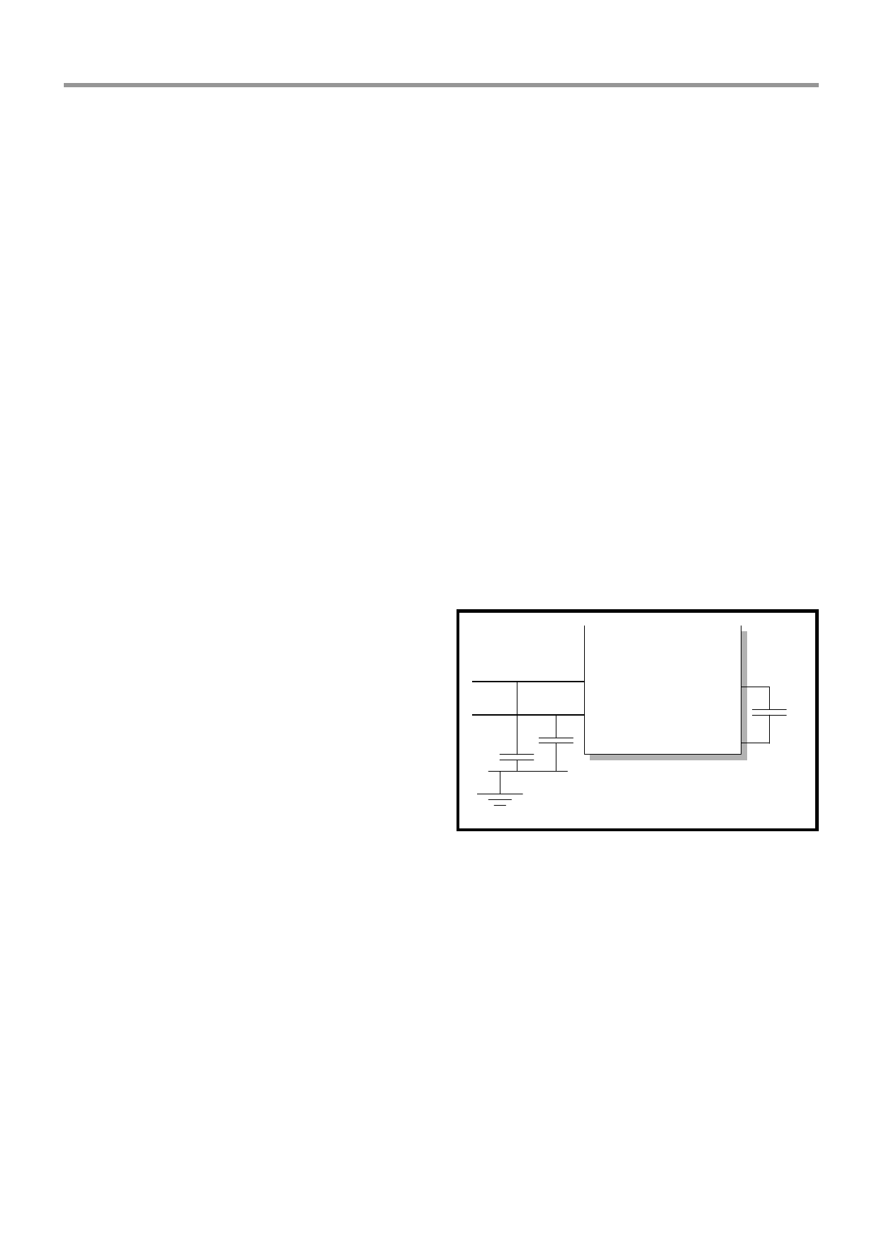
In some applications, additional EMI suppression may
be needed. In this instance 3 capacitors can be added
to filter out the higher frequencies of the DC-DC
converter. See figure 6 for details.
1nF
1nF
AAg11117700
Tip
Ring
ZB
VOUT
100pF
Figure 6: Optional EMI Suppression
7.0 A Typical Application.
The Ag1170 has been designed to interface to any
Codec. Applications drawings for many codecs and
DSP chips are available. Please contact Silver
Telecom or visit our website www.silvertel.com. An
example is shown in figure 5.
The status outputs from the SLIC are passed to the
micro-controller. These signals can then be processed
as necessary by the system software.
The audio signals which are on the 4 wire side of the
connection are coupled by 100nF capacitors to avoid
d.c. level problems between the two devices.
© Silver Telecom 2006
9
Share Link: 