AK2510 데이터 시트보기 (PDF) - Asahi Kasei Microdevices
부품명
상세내역
제조사
AK2510 Datasheet PDF : 16 Pages
| |||
ASAHI KASEI
[AK2510]
2-2 16 bit Linear PCM data mode
In this mode the 16 bit linear PCM data are interfaced to the outside. This mode is useful to compress/extend the
PCM data using much higher compress rate algorithm than u/A-law algorithm by the external DSP. The AK2510
operates at 14bit accuracy, thus the least 2 bits are output as fixed value.
2-2-a Signals
- Frame Sync signal (FS)
8kHz reference signal which is same as in u/A-law PCM data mode. The FS pulse H level width should be 1 clock
period as same as in the short frame PCM mode.
- Bit Clock (BCLK)
BCLK defines the PCM data rate. BCLK can be varied from 512kHz or 2.048MHz which is different from in the
u/A-law PCM data mode.
- PCM data output (TOUT, ROUT)
TOUT and ROUT are output signal of 128Kbps linear PCM data. The data is synchronized to the BCLK which
determines the data rate. In the period in which the PCM data is not occupied, the TOUT and ROUT pins turns to
Hi-impedance output.
- PCM data input (TIN, RIN)
TIN and RIN are input signal of 128Kbps linear PCM data. The data is clocked by the falling edge of the BCLK
and fed into the PCM interface block.
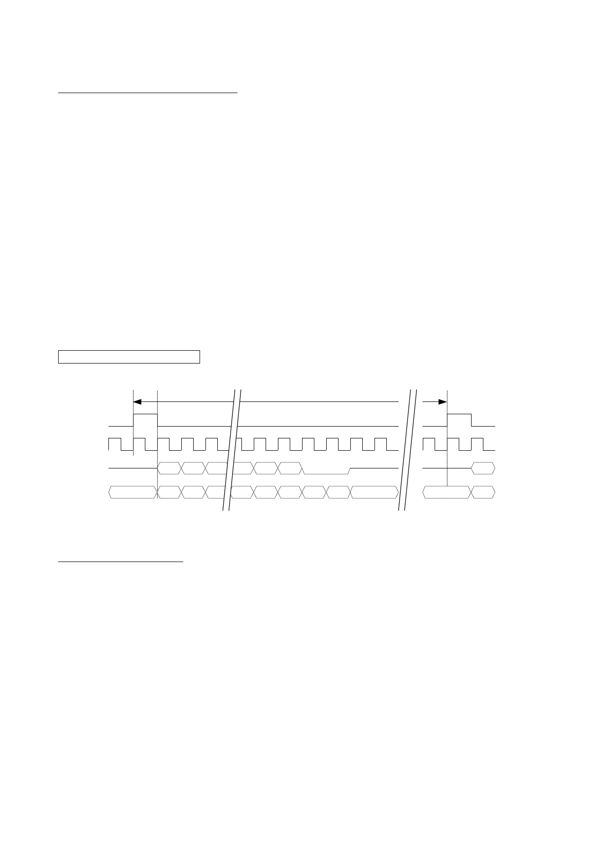
16bti Linear Frame format
125us (8KHz)
FS
BCLK
MSB First
DX
Hi-Z
15 14 13 2 1 0
Hi-Z
MSB First
DR
*
15 14 13 2 1 0 * *
*
Hi-Z
15
*
14
2-3 AK130 B1/B2 Mode
These modes are for connecting the PCM interface to AK130, AKM’s TCM( ping-pong ) transceiver for PBX/KTS
system. The PCM data format is A-law or u-law which can be selected by the register. The AK130 B1 mode
interfaces the data to B1 channel, one of the B channel which AK130 provides, and t he AK130 B2 mode interfaces
the data to B2 channel.
2-3-a Signals
- Frame Sync signal (FS)
___
Please feed the FS signal which is generated by the AK130.( F0o , pin#3 )
- Bit Clock (BCLK)
BCLK defines the PCM data rate. Please use 2.048MHz clock which is generated by the AK130.( E2o,pin#5 )
- PCM data output (TOUT, ROUT)
TOUT and ROUT are output signal of 64Kbps PCM data. Please connect the ROUT to the PCM data input pin of
AK130. ( DSTi,pin#11 )
- PCM data input (TIN, RIN)
TIN and RIN are input signal of 64Kbps PCM data. The data is clocked by the falling edge of the BCLK and fed
into the PCM interface block. Please connect the RIN to the PCM data output pin of AK130. ( DSTo,pin#6 )
AKM
- 10 -
AK2510-E-00
Share Link: 