PDM41256 데이터 시트보기 (PDF) - Paradigm Technology
부품명
상세내역
제조사
PDM41256 Datasheet PDF : 8 Pages
| |||
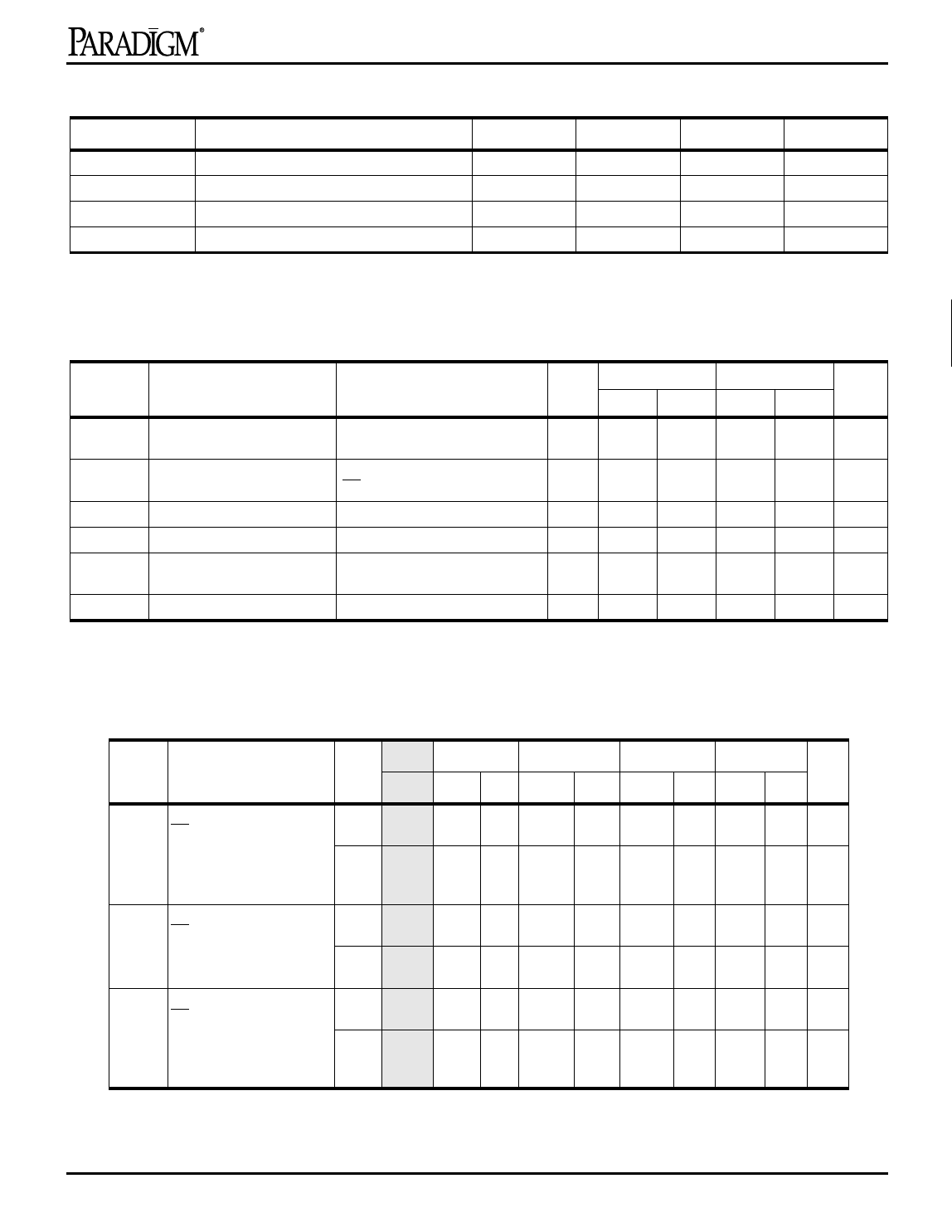
Recommended DC Operating Conditions
Symbol
Parameter
VCC
VSS
Commercial
Industrial
Supply Voltage
Supply Voltage
Ambient Temperature
Ambient Temperature
PDM41256
Min.
Typ.
Max.
Unit
4.5
5.0
5.5
1 V
0
0
0
V
0
25
70
°C
–40
25
85
°C
2
DC Electrical Characteristics (VCC = 5.0V ± 10%)
Symbol
ILI
Parameter
Input Leakage Current
Test Conditions
VCC = MAX., VIN = Vss to VCC
ILO
Output Leakage Current
VCC= MAX.,
CE = VIH, VOUT = Vss to VCC
VIL
Input Low Voltage
VIH
Input High Voltage
VOL
Output Low Voltage
IOL=8 mA, VCC = Min.
IOL = 10 mA, VCC = Min.
VOH
Output High Voltage
IOH = –4 mA, VCC = Min.
NOTE: 1. VIL(min) = –3.0V for pulse width less than 20 ns.
3
PDM41256SA PDM41256LA Unit
Min. Max. Min. Max.
Com’l/ –5
5
–1
1
µA
4
Ind.
Com’l/ –5
5
–1
1
µA
Ind.
–0.5(1)
0.8
–0.5(1)
0.8
V
5
2.2
6.0
2.2
6.0
V
—
—
0.4
0.5
—
—
0.4
0.5
V
6
2.4
—
2.4
—
V
7
Power Supply Characteristics
-7
-8
-10
-12
-15
Symbol Parameter
Power Com’l. Com’l. Ind. Com’l. Ind. Com’l. Ind. Com’l. Ind. Units
ICC
Operating Current
CE = VIL
SA 210 200 210 190 200 170 180 150 160 mA
f = fMAX = 1/tRC
VCC = Max
IOUT = 0 mA
LA 190 180 190 170 180 150 160 130 140 mA
ISB
Standby Current
CE = VIH
SA 90
80 80 70
70
60 60 50 50 mA
f = fMAX = 1/tRC
VCC = Max
LA
90
80 80 70
70
60 60 50 50 mA
ISB1
Full Standby Current
CE ≥ VCC – 0.2V
SA 20
20 20 20
20
20 20 20 20 mA
f=0
LA
5
5
5
5
5
5
5
5
5 mA
VCC = Max
VIN ≥ VCC – 0.2V or ≤ 0.2V
SHADED AREA = PRELIMINARY DATA
NOTE:All values are maximum guaranteed values.
8
9
10
11
12
Rev. 4.4 - 4/29/98
3
Share Link: 