AN246 데이터 시트보기 (PDF) - Philips Electronics
부품명
상세내역
제조사
AN246 Datasheet PDF : 13 Pages
| |||
Philips Semiconductors
Transmission lines and terminations
with Philips Logic families
Application Note
AN246
Author: Mike Magdaluyo, Logic Products Group
INTRODUCTION
With increasing systems speeds and faster logic families,
interconnect characteristics have become significant. The signal
transition times of faster families can increase transmission line
effects on printed circuit board traces and cables. If not taken into
consideration, signal degradation can cause data errors in a system.
Previous logic families with slower rise and fall times such as LS
and HCMOS were not as severely affected by this issue if line
lengths were not too long. For example, an HCMOS buffer with a 5
ns edge will start exhibiting transmission line effects when a circuit
board trace is longer than a foot. However, with newer families, even
relatively short trace lengths become very important. This
application note will briefly review transmission line concepts and
evaluate transmission line effects with Philips 5 volt and 3 volt
BiCMOS and CMOS logic families such as ABT, AC(T), ALVC, LVC,
LVT, and ALVT.
For more detailed information on transmission lines, there are many
other resources to refer to. The terms line or transmission line will
refer to a cable or printed circuit trace medium and will be regarded
as equivalent for electrical purposes, though their construction
varies in real applications.
CRITICAL LINE LENGTH
An interconnect is considered electrically long when the round trip
propagation delay of the interconnect from the driver to the load is
equal to or greater than the transition time of the driver’s rise or fall
time. At this point, transmission line effects become significant.
Using 160ps per inch as a nominal propagation delay for 50 Ω
stripline medium and a nominal 0.9 ns rise time for a lightly loaded
ABT driver with 15 pF loading, the critical line length is
Eq. 1
Critical line length + 2
+2
tpd
tr
160 ps ń in.
0.9 ns
+ 2.8 in.
For this example, traces shorter than this can be treated as lumped
elements. Traces equal to or longer than this length should be
modeled as distributed elements. Table 1 shows critical line lengths
at various line impedances for different Philips’ logic families.
Assumptions are light loading of 15 pF and a nominal 8 nH per inch
characteristic inductance for a PC board trace. Formulas to
determine line impedance are shown in the following section.
Table 1. Maximum trace length in inches with
15pF loading
Family
tr
ns
tf 100 70
ns
Ω
Ω
50
Ω
35
Ω
25
Ω
HC
2.9 2.9 18.1 12.7 9.1 6.3 4.5
AHC
AC
ALS
FAST
ABT
LVT
ALVT
2.1 1.6 10.0 7.0 5.0 3.5 2.5
1.2 1.7 7.5 5.3 3.8 2.6 1.9
2.7 1.7 10.6 7.4 5.3 3.7 2.7
4.0 1.4 8.8 6.1 4.4 3.1 2.2
0.9 1.2 5.6 3.9 2.8 2.0 1.4
0.8 0.6 3.8 2.6 1.9 1.3 0.9
0.8 0.7 4.4 3.1 2.2 1.5 1.1
LVC
LV
ALVC
1.8 1.8 11.3 7.9 5.6 3.9 2.8
2.9 2.9 18.1 12.7 9.1 6.3 4.5
1.2 1.1 6.9 4.8 3.4 2.4 1.7
As you can see, using faster edge families even with relatively short
traces still requires consideration of transmission line effects.
CHARACTERISTIC LINE IMPEDANCE AND
CAPACITIVE LOADING
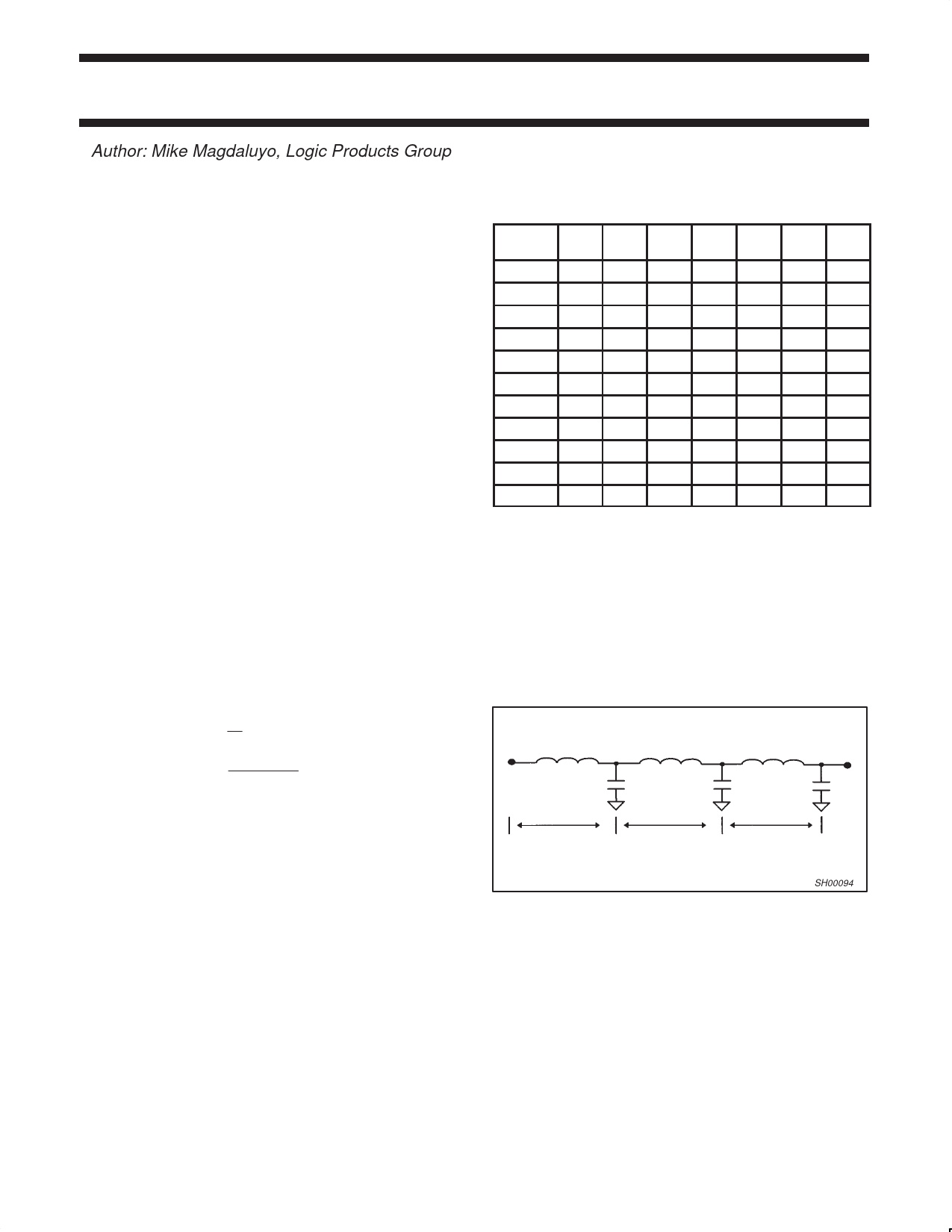
A transmission line has distributed series inductance and distributed
capacitance throughout its length, and can be modeled as shown in
Figure 1. The line has characteristic inductance and capacitance
per unit length, l, where LO is in Henries per inch, and CO is in
farads per inch.
L0
C0
l
L0
C0
l
L0
C0
l
SH00094
Figure 1. Circuit equivalent for a transmission line
1998 Feb 05
2
Share Link: 