AN1013 데이터 시트보기 (PDF) - STMicroelectronics
부품명
상세내역
제조사
AN1013 Datasheet PDF : 13 Pages
| |||
AN1013
APPLICATION NOTE
INTRODUCTION
MONO CLASS_D AMPLIFIERS
by M. Masini, L. Pagotto
The TDA7480/81/82 are single ended , split supply, class_D amplifiers. The output of the amplifier is a
high frequency square wave (around 100Khz), rail to rail, with variable duty cycle.
The audio information is the average value of the output square wave.
To obtain the audio signal, the output must be low pass filtered.
The main issue of this amplifier is the very low dissipated power (the very high efficiency) compared to a
normal class AB amplifier.
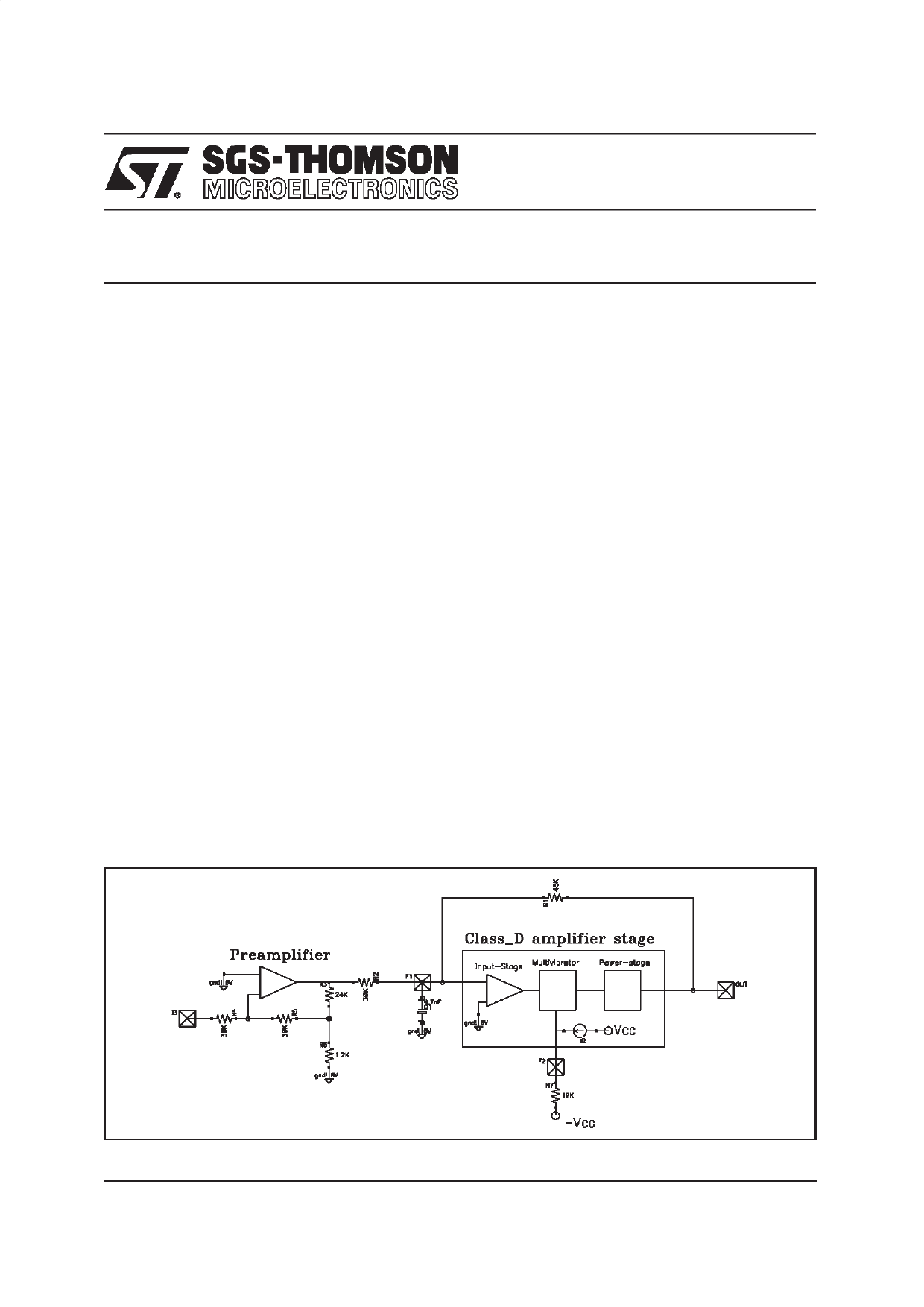
The preamplifier provides the voltage gain of the overall amplifier. The second stage is the power stage,
with a gain 1.5, that is the high efficiency class_D amplifier.
The class_D amplifier stage is done with a multivibrator : with no signal it generates a 50% duty cycle
square wave, with signal applied, it changes the duty cycle.
The switching frequency is set by the voltage on pin 9 (DIP20) or pin 6 (MW15).
The output power stage is done with N-ch DMOS power with the upper one supplied by a bootstrap ca-
pacitor (C11 in the application circuit).
1. CRITICAL COMPONENTS IN THE APPLICATION
A: Bypass high frequency filtering capacitor on supply
The most important filter capacitor is C5 (see application circuit) between pin 13/14 for MW15 package
or pin 16/17 for DIP20 package.
The value of the parasitic inductance between this capacitance and the IC pins is related to the ampli-
tude of the spikes on the power supply pins at every commutations of the output.
In fact, for any commutation, there is an abrupt variation of the current in the parasitic inductances Lpar
in series to the supply. This abrupt variation increases as the output current increases and can be typi-
cally of some amperes on 10ns. With this slew rate of the current, also an inductance of about some the
of nH (i.e. the lead inductance of the pin) generates voltage spikes of some volts.
Figure 1. Block Diagram
February 1998
1/13
Share Link: 